
Phase-Locked Loop Circuit

The Phase-Locked Loop (PLL) is a critical component in various electronic systems, particularly in communication and signal processing. It functions by locking onto the frequency and phase of an input signal, enabling the generation of stable output waveforms. In this configuration, the PLL can produce both triangle and square wave outputs, which are essential for different applications, including modulation and waveform generation.
The use of a quad operational amplifier in this circuit enhances its versatility and performance. Quad op-amps, which contain four independent op-amps in a single package, provide the necessary signal conditioning and amplification required for effective PLL operation. They are particularly beneficial in audio and low-frequency (LF) radio applications, where signal integrity and fidelity are paramount.
In a typical PLL circuit, the input signal is fed into a phase detector, which compares the phase of the input signal with that of a feedback signal derived from the output. The phase detector generates an error signal that is then filtered and used to adjust the voltage-controlled oscillator (VCO). The VCO generates the output signal, which is fed back to the phase detector to maintain synchronization.
The triangle wave output can be utilized in applications requiring linear modulation, while the square wave output is suitable for digital signal processing and clock generation. The selection of output type is determined by the specific requirements of the application, whether it be for audio synthesis, frequency modulation, or other signal processing tasks.
Overall, this PLL configuration with a quad op-amp is a robust solution for generating stable waveforms across a range of frequencies, making it an invaluable tool in modern electronic design. The PLL will lock onto an input signal. Both triangle- and square-wave outputs are available. A quad op amp can be used in this circuit, which should be useful in the audio and LF radio region.
Related Circuits
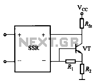
A DC solid-state relay (DC-SSR) driving a high-power load circuit is illustrated in (a) below; the high-power load driving circuit is depicted in (b) below. The DC solid-state relay (DC-SSR) serves as a crucial component in controlling high-power loads, providing...
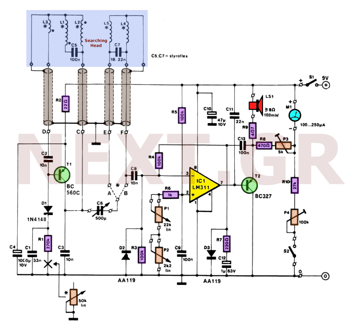
Metal detectors can be categorized based on their operational principles into three types: BFO (Beat Frequency Oscillator), TR/IB (Transmit-Induction/Balance), and PI (Pulsed Induction). Each method has its own set of advantages and disadvantages. An ideal metal detector, which does...
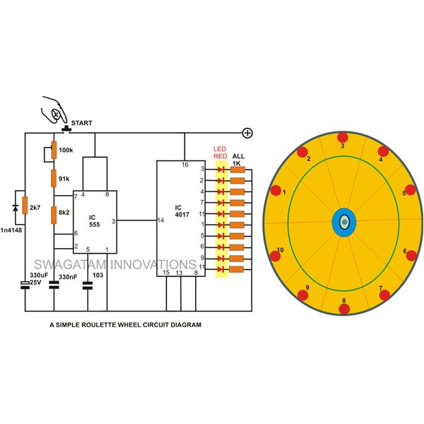
A simple circuit for a 10 LED roulette wheel is presented. Pressing the button initiates the LEDs in a rotational sequence that starts at full speed and gradually decelerates until it halts at a randomly selected LED. The randomness...
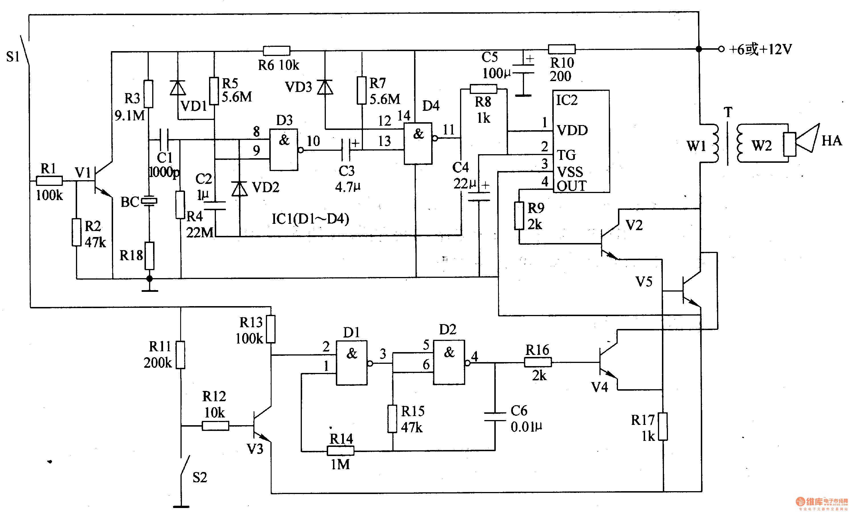
The motorcycle anti-theft alarm circuit consists of several components, including the anti-theft detection circuit, the control circuit, the sound generator, the audio oscillator, and the power amplifier output circuit, as illustrated in figure 7-91. The anti-theft detection circuit is...
Gadget Master provides the latest updates on capacitance circuits in a compilation of capacitance circuit projects and websites tailored for electronics designers, scientists, and engineers. Capacitance circuits are fundamental in various electronic applications, serving critical roles in timing, filtering, and...
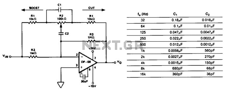
This circuit represents a section of an octave equalizer utilized in audio systems. The table outlines the values of C1 and C2 required to achieve specific center frequencies. This circuit can provide a boost or cut of 12 dB,...