
Magnetic Field Meter
The described circuit utilizes a pickup coil as the primary sensing element, which is connected to an amplifier integrated circuit (IC3A-B-C-D). The amplifier is responsible for amplifying the signal generated by the coil, which is sensitive to electromagnetic fields. The calibration of the meter circuit allows for direct measurement in field intensity units, making it suitable for various applications in electromagnetic field detection.
The components R3 and C3, along with R12 and C7, form a low-pass filter that serves to manage the frequency response of the circuit. This configuration ensures that high-frequency noise is attenuated, allowing for a more accurate representation of the desired signal. The cut-off frequency is set at 20 kHz, which is critical for ensuring that the circuit can effectively respond to the expected frequency range of interest, which spans from 50 Hz to 20 kHz.
The range-select switch, S2, enables the user to select different measurement ranges, enhancing the versatility of the device. This feature is particularly important for applications requiring measurements at varying field intensities, as it allows for both low and high sensitivity measurements.
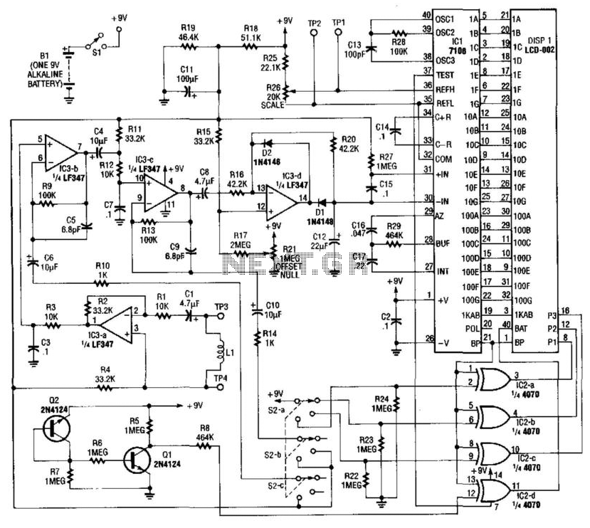
The pickup coil, designated as L1, is constructed with 18 turns of wire wound into a 3-inch diameter configuration. This design optimizes the coil's sensitivity to magnetic fields, making it effective for detecting low-intensity signals. The overall measurement range of the circuit is from 0.1 µT to 20,000 µT, accommodating a wide spectrum of electromagnetic field strengths.
In summary, this circuit is designed for precise measurements of electromagnetic fields, with a well-defined frequency response and user-selectable measurement ranges, making it a valuable tool for field applications in electromagnetic field analysis. Using a pickup coil to drive an amplifier (IC3A-B-C-D), this meter circuit can be directly calibrated in field-intensi ty units. R3/C3 and R12/C7 establish a frequency roll off that compensates for the pickup-coil sensitivity, and set a 20-kHz cut-off point. S2 is the range-select switch. Ll is an 18-turn 3" diameter coil. The frequency range is 50 Hz to 20 kHz and the range of measurement is 0.1 to 20 000 microTesiers (uT).
🔗 External reference
Related Circuits
This circuit is designed for precise centigrade temperature measurement. It features a transmitter section that converts the sensor's output voltage, which is proportional to the measured temperature, into frequency. The output frequency bursts are transmitted through the mains supply...
The circuit presented is designed to prevent burning one's tongue by monitoring the temperature of coffee. It consists of a voltage regulator, a temperature-to-voltage converter, a comparator, and two LEDs. In general, the circuit operates as follows: if the...
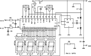
The ICL7107 is a 3 1/2 digit LED analog-to-digital converter (A/D converter). It features an internal voltage reference, high-isolation analog switches, sequential control logic, and display drivers. The ICL7107 is designed to convert analog signals into digital representations with a...
This circuit is a digital voltmeter with an LED display, ideal for measuring the output voltage of a DC power supply. It features a 3.5-digit LED display with a negative voltage indicator and measures DC voltages from 0 to...
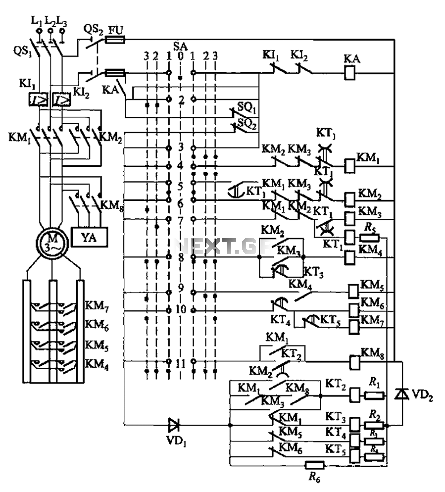
The system involves a master controller and a PQS1 Series Magnetic control panel, which includes a control circuit designed to manage the bridge crane hoist lifting mechanism. The master controller handle SA features seven positions: alongside the zero position,...
This circuit is an Audio Decibel Level Meter that utilizes the SA604 integrated circuit, which is designed as an RF device and also serves as a Received Signal Strength Indicator (RSSI). In cellular radio applications, the radio's microcomputer continuously...