
Crystal oscillator and frequency divider 74LS04 schematic

The circuit diagram for a crystal oscillator combined with a frequency divider utilizing the 74LS04 integrated circuit is designed to generate a stable clock signal. The crystal oscillator component typically consists of a quartz crystal, which is connected in parallel with the input of the inverter gates within the 74LS04. The inverter gates are used to create a feedback loop that enables oscillation at the crystal's resonant frequency.
In this configuration, the crystal is connected between the output of one inverter and the input of another, establishing a feedback mechanism that sustains oscillation. The frequency of oscillation is determined by the characteristics of the crystal and the associated passive components, such as capacitors, which may be connected to ground to stabilize the frequency.
The 74LS04 contains six inverters, allowing for multiple stages of frequency division if required. The output from the oscillator can be fed into additional inverters to achieve the desired frequency division. Each subsequent inverter stage effectively divides the frequency by two, resulting in a series of square wave outputs at frequencies that are halved with each stage.
The circuit's power supply should be connected to the Vcc pin of the 74LS04, while the ground pin should connect to the circuit's common ground. Proper decoupling capacitors should be placed close to the power supply pins to filter out noise and ensure stable operation.
This configuration is widely used in various applications, including clock generation for digital circuits, timers, and frequency modulation systems, due to its simplicity and reliability in producing precise frequency outputs.Crystal oscillator and frequency divider (74LS04) circuit diagram:
Related Circuits
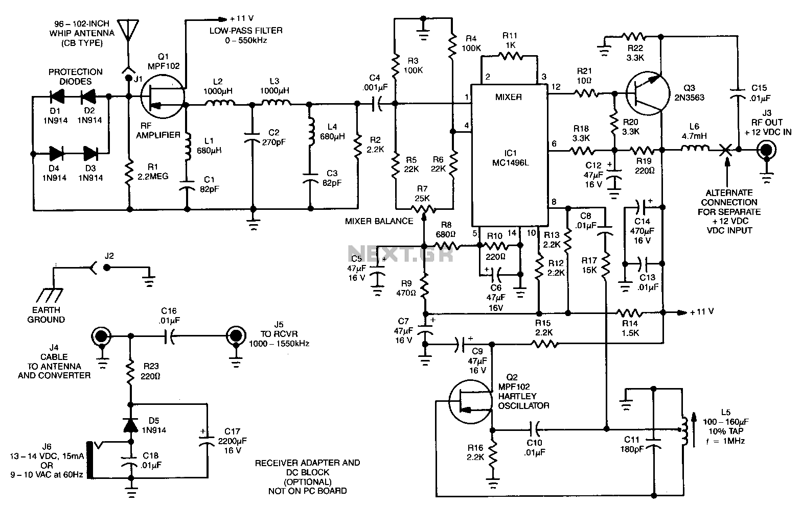
The signals below 550 kHz include maritime mobile, distress signals, radio beacons, aircraft weather information, European Longwave-AM broadcasts, and point-to-point communications. A low-frequency converter transforms the 10 to 500 kHz LW range into a 1010 to 1550 kHz MW...
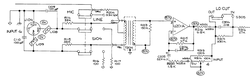
A student is working on a project related to active electronics as part of their second year in a bachelor's program in audio production. Active electronics refers to electronic circuits that require an external power source to operate, typically involving...

The two circuits illustrate the generation of low-frequency sine waves by shifting the phase of the signal through an RC network, enabling oscillation when the total phase shift reaches 360 degrees. The transistor circuit on the right produces a...
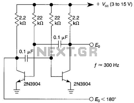
This free-running square-wave oscillator utilizes two NPN transistors. The output frequency is approximately 300 Hz with the specified component values. The circuit operates as a basic oscillator, generating a square wave output through the interaction of two NPN transistors. The...
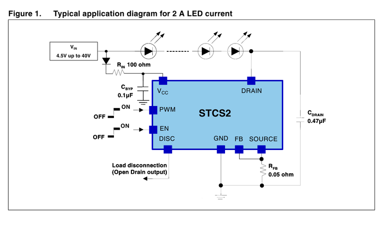
A driver based on the STCS2 for a 445nm laser is being developed. The STCS2 was selected due to its low voltage drop, and the power supply will consist of two lithium-ion cells. The STCS2 is a highly efficient, low-dropout...
Most frequency multiplier circuits utilize an integrated circuit (IC) phase-locked loop (PLL). These circuits typically increase the frequency by an integer factor only. However, this particular circuit is capable of doubling the frequency. Frequency multiplier circuits are essential in various...