
A frequency multiplier in depth

Frequency multiplier circuits are essential in various applications where signal frequency needs to be increased for better performance or functionality. The phase-locked loop (PLL) is a fundamental component in these circuits, as it synchronizes the output frequency to a reference frequency input.
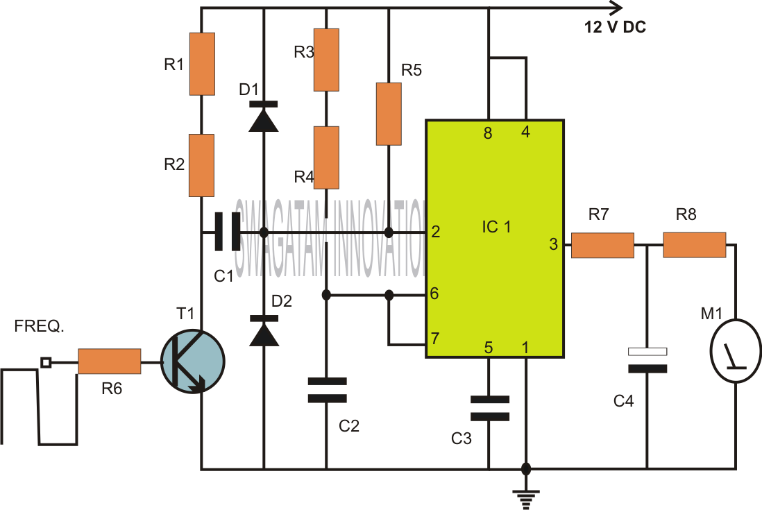
In this specific frequency doubling circuit, the PLL is configured to achieve a multiplication factor of two. The core components include a voltage-controlled oscillator (VCO), a phase comparator, and a loop filter. The VCO generates a frequency that is controlled by the input signal. The phase comparator compares the phase of the input signal with the VCO output and generates an error signal that drives the loop filter. The loop filter smooths this error signal to provide a stable control voltage to the VCO, ensuring that the output frequency is precisely double that of the input frequency.
The circuit design may also incorporate additional features such as frequency stability enhancements, noise reduction techniques, and output buffering to ensure the doubled frequency signal maintains integrity across various loads and conditions. Proper layout considerations, including minimizing parasitic capacitance and inductance, are crucial in achieving optimal performance in high-frequency applications.
This frequency doubling circuit using a PLL is widely applicable in communication systems, RF transmission, and signal processing where precise frequency control is paramount.Most of the frequency multiplier circuit using IC phase locked loop (PLL).It will increase the frequency to an integer only. But this circuit can double the.. 🔗 External reference
Related Circuits
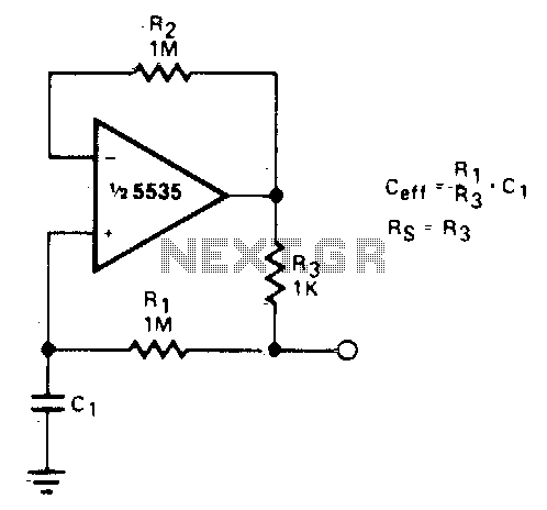
This circuit can be used to simulate large capacitances using small value components. With the values shown and C = 10 µF, an effective capacitance of 10,000 µF was obtained. The quality (Q) available is limited by the effective...
The two circuits below illustrate the generation of low-frequency sine waves by shifting the phase of the signal through an RC network, ensuring that oscillation occurs when the total phase shift reaches 360 degrees. The transistor circuit on the...
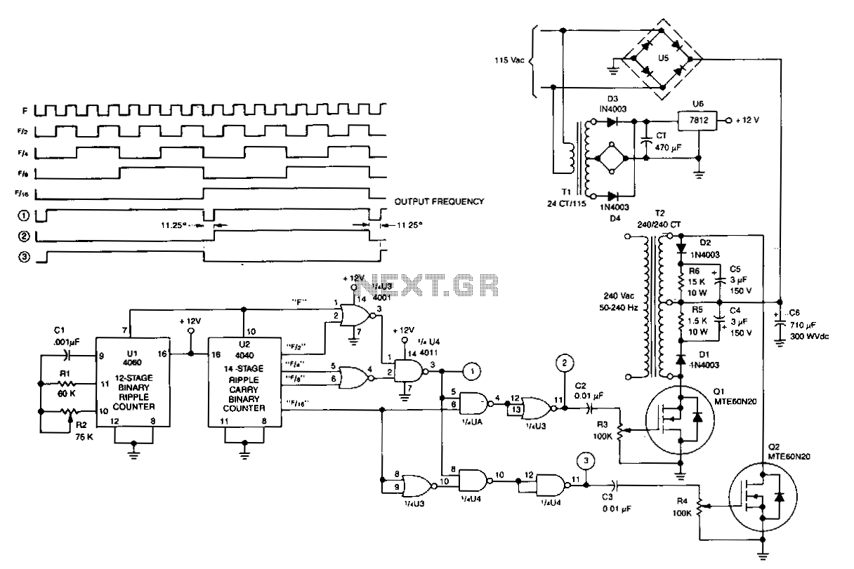
U1 is a 4060 12-stage binary ripple counter that operates as a free-running oscillator, with its frequency of oscillation calculated as 1/2.2 CIR2. The output from U1 is fed into U2, a 14-stage binary ripple counter that generates square-wave...
Capacitors are major electronic components classified as passive components. They are extensively used in electronic circuits, and virtually no circuit can be constructed without these essential parts. The primary function of a capacitor is to block direct current (DC)...
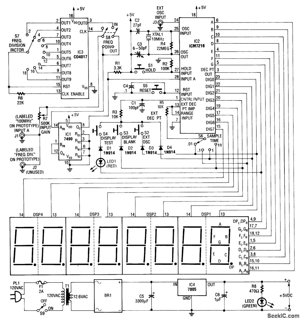
Built around an Intersil 7216 frequency-counter IC, this counter features a basic frequency range of 10 MHz, complemented by a 100-MHz prescaler and an additional frequency divider (IC3). This divider further extends the counting range by dividing the frequency...
The RF engineer sometimes needs an instrument that can reliably and quickly test a low-frequency quartz crystal unit. Finding such equipment can be challenging, and engineers often refer to electronic circuit handbooks for schematics that can perform this task....