
Pressure sensor circuit with a filtering and amplification circuit diagrams
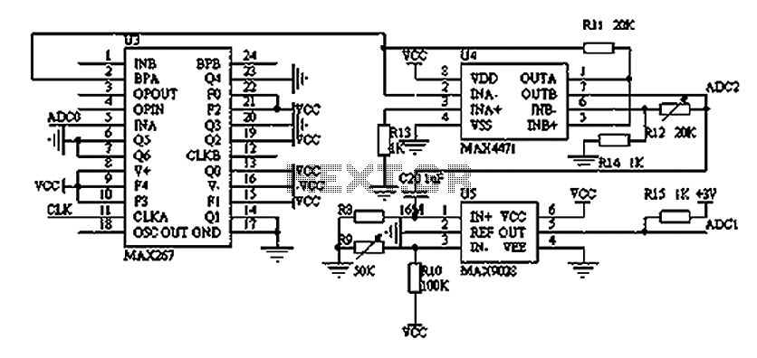
The filtering and amplifying circuit is designed for precision in monitoring blood pressure by effectively managing signal integrity. The MAX267 integrated circuit serves as the primary filtering component, configured to operate as a band-pass filter that specifically allows low-frequency signals characteristic of blood pressure waveforms while rejecting unwanted high-frequency noise and DC offsets. This is critical in medical applications where accurate readings are necessary.
The MAX4471 amplifier follows the filtering stage, providing necessary gain to the filtered signal. This low-power amplifier is chosen for its efficiency, making it suitable for battery-operated devices. It ensures that the signal level is sufficient for further processing without introducing significant noise or distortion.
The output from the MAX4471 is directed to an analog-to-digital converter (ADC2), which digitizes the AC component of the blood pressure signal for digital processing and analysis. This step is essential for converting the analog signal into a format that can be easily manipulated and displayed by microcontroller-based systems.
Simultaneously, the MAX9028 comparator plays a crucial role in generating a pulse signal from the amplified output. This pulse signal is used to trigger another ADC (ADC1), which may be responsible for capturing different aspects of the blood pressure waveform or for timing purposes in the overall measurement cycle. The use of a comparator allows for precise timing and synchronization in the data acquisition process.
Overall, this circuit exemplifies a sophisticated approach to biomedical signal processing, integrating multiple components to ensure accurate, reliable, and efficient blood pressure monitoring. The design considerations include low power consumption, high performance, and the ability to filter out noise, making it suitable for use in portable medical devices.As illustrated, the filtering and amplifying circuit composed of two parts. Wherein the filter MAXIM MAX267 is an integrated company produced, may constitute a low-pass, band p ass, high pass, and other methods, the use of flexible, performance is far superior to filter integrated circuit op amp. MAXIMs MAX4471 is a low-power amplifier. MAXIMs MAX9028 is a low-power comparator. Filter circuit MAX267 constitute a band pass filter (0.8 ~ 38Hz signal allowed through), filter out the DC component of the signal and power supply and high-frequency noise and workers skin friction with the cuff frequency interference, and then after MAX4471 for further amplification, SCM get matching voltage signal into ADC2, the AC component of blood pressure monitoring.
Meanwhile, the signal passes through a low-power comparator MAX9028 converted into a pulse signal to trigger ADC1 work.
Related Circuits
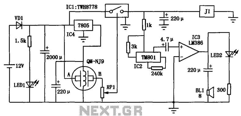
The alcohol detection alarm controller circuit is illustrated in the figure. It utilizes the QM-NJ9 alcohol gas sensor, which detects the presence of alcohol vapors. When alcohol is detected, the resistance between the AB-QM-NJ9 decreases, causing the wiper of...
The following circuit illustrates a Water Level Detector Circuit Diagram. This circuit is based on the PIC12F683 microcontroller. Features include the ability of the PIC microcontroller to enter a sleep mode. The Water Level Detector Circuit utilizing the PIC12F683 microcontroller...
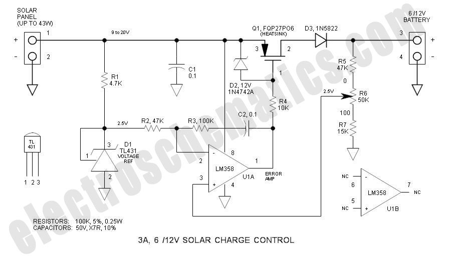
This solar charge controller integrates multiple features into a single design, including a 3A current rating, low dropout voltage (LDO), and a range of voltage adjustment capabilities. The solar charge controller is a critical component in solar energy systems, tasked...
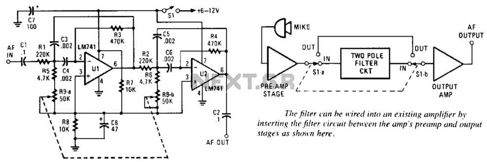
This variable-frequency audio bandpass filter is constructed using two 741 operational amplifiers (op amps) connected in cascade. Both op amps are configured as identical RC active filters, enhancing the selectivity of the overall circuit. The filter has a tuning...
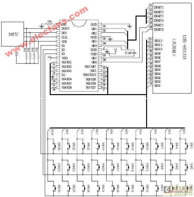
The ET6201 is a LED display control drive circuit with a duty cycle of 1/7 to 1/8. It features 11 segment output gates and 1 segment/gate output, along with a display memory, control circuit, and key scanning circuit, which...
The SFH505A, manufactured by Siemens, integrates an infrared diode receiver, amplifier, demodulator, and a band-pass filter to minimize interferences. This circuit operates effectively in various applications. The SFH505A is a versatile optical receiver module designed for infrared communication systems. It...