


True rms detector
#rms detector
#voltage measurement
#signal processing
#filter capacitor
#accuracy
#frequency range
#dc output
#input signal
#instrumentation
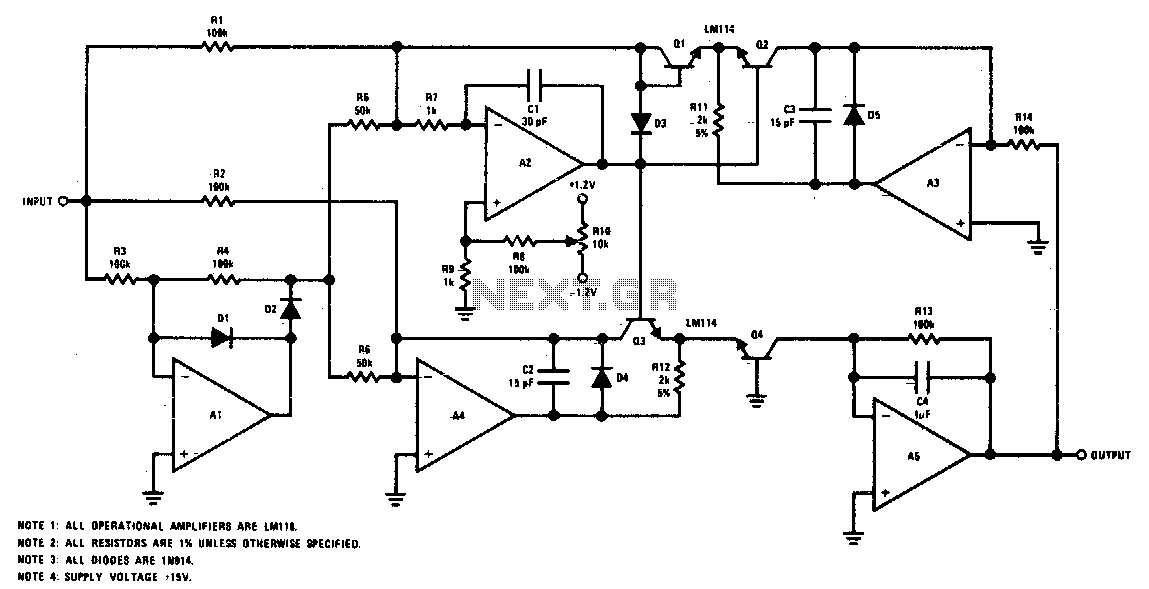
Description: The circuit provides a DC output that corresponds to the RMS value of the input. The accuracy is typically 2% for a 20 Vpp input signal within the frequency range of 50 Hz to 100 kHz, although it remains functional up to approximately 500 kHz. The lower frequency limit is determined by the size of the filter capacitor. Additionally, because the input is DC coupled, the circuit can accurately deliver the true RMS equivalent of both DC and AC signals.
The described circuit functions as a true RMS converter, which is essential for measuring the effective value of varying AC signals in a DC format. The circuit's design typically incorporates a precision rectifier to ensure accurate representation of the input signal's RMS value. This rectifier is often followed by a low-pass filter, which smooths the output to provide a stable DC voltage that corresponds to the RMS value.
In terms of components, the circuit generally includes operational amplifiers configured for rectification, precision resistors for maintaining accuracy, and a filter capacitor that plays a crucial role in determining the lower frequency response. The size of the filter capacitor directly influences the cutoff frequency of the low-pass filter, with larger capacitors allowing for lower frequency signals to be processed effectively.
The operational amplifiers used in the circuit must have a high slew rate and bandwidth to accommodate the specified frequency range, especially since the circuit is capable of handling frequencies up to 500 kHz. Additionally, the choice of precision resistors is critical to maintain the stated accuracy of 2%, ensuring minimal error in the output voltage.
Overall, this circuit is particularly useful in applications where accurate RMS measurements of AC signals are required, such as in power monitoring systems, audio equipment, and various electronic testing environments. Its ability to handle both AC and DC inputs makes it versatile for a range of electronic applications.The circuit will provide a dc output equal to the rms value of the input. Accuracy is typically 2% for a 20 Vpp input signal from 50 Hz to 100 kHz, although it"s usable to about 500 kHz. The lower frequency is limited by the size of the filter capacitor Since the input is dc coupled, it can provide the true rms equivalent of a dc and ac signal.
The described circuit functions as a true RMS converter, which is essential for measuring the effective value of varying AC signals in a DC format. The circuit's design typically incorporates a precision rectifier to ensure accurate representation of the input signal's RMS value. This rectifier is often followed by a low-pass filter, which smooths the output to provide a stable DC voltage that corresponds to the RMS value.
In terms of components, the circuit generally includes operational amplifiers configured for rectification, precision resistors for maintaining accuracy, and a filter capacitor that plays a crucial role in determining the lower frequency response. The size of the filter capacitor directly influences the cutoff frequency of the low-pass filter, with larger capacitors allowing for lower frequency signals to be processed effectively.
The operational amplifiers used in the circuit must have a high slew rate and bandwidth to accommodate the specified frequency range, especially since the circuit is capable of handling frequencies up to 500 kHz. Additionally, the choice of precision resistors is critical to maintain the stated accuracy of 2%, ensuring minimal error in the output voltage.
Overall, this circuit is particularly useful in applications where accurate RMS measurements of AC signals are required, such as in power monitoring systems, audio equipment, and various electronic testing environments. Its ability to handle both AC and DC inputs makes it versatile for a range of electronic applications.The circuit will provide a dc output equal to the rms value of the input. Accuracy is typically 2% for a 20 Vpp input signal from 50 Hz to 100 kHz, although it"s usable to about 500 kHz. The lower frequency is limited by the size of the filter capacitor Since the input is dc coupled, it can provide the true rms equivalent of a dc and ac signal.
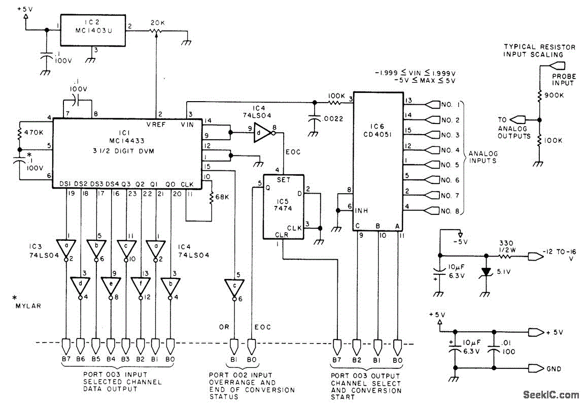
EIGHT CHANNEL COMPUTERIZED 3SUP1 SUP SUB2 SUB DIGIT_VM
Displays up to eight different DC voltages on a CRT terminal of a microprocessor under keyboard control, using BASIC commands and a BASIC routine provided in the article. Utilizes a modified Motorola MC14433 dual-lamp integrating analog-to-digital converter. An unknown voltage...
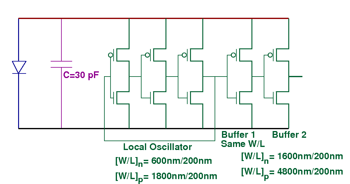
The Measurements for MIT 3DL1 Run
The chips that are classified as "working well" produce approximately 300 mV when exposed to a laser pointer and between 40 to 80 mV when illuminated by LED light. Voltages around 100 mV were recorded in a sunlit environment, while...
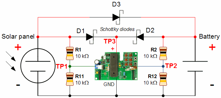
Circuit to Measure Power Supply Voltages
To obtain the power supply graphs on the previous page, the circuit is designed to independently monitor the power sources with the addition of a few resistors. Diode D3 allows the solar panel voltage to charge the batteries, while the...
Interpolating Scanner Circuit
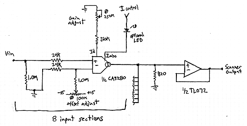
This design is for an interpolating scanner, a circuit featuring multiple signal inputs, a control voltage input, and a signal output. The output selectively transitions between inputs, smoothly fading from one to the next as the control voltage increases. A...
Instrumentation circuit
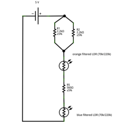
The mechanical chassis prototype, as illustrated in the accompanying image, was constructed using two materials: foam and aluminum. Foam was selected for its ease of manipulation, while aluminum was chosen for its excellent strength-to-weight ratio. The prototype features a rotary...
Test-Measurement 4
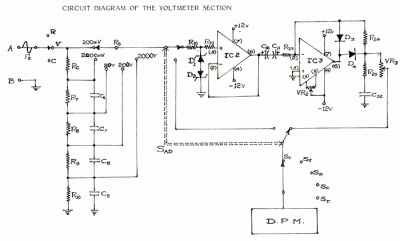
In circuit diagrams provided in equipment manuals, voltages at various points in the circuit are typically indicated. A deviation from these specified values suggests that a component has failed and can help in identifying faulty areas. Specifications include: D.C. Voltage...
Coulomb meter
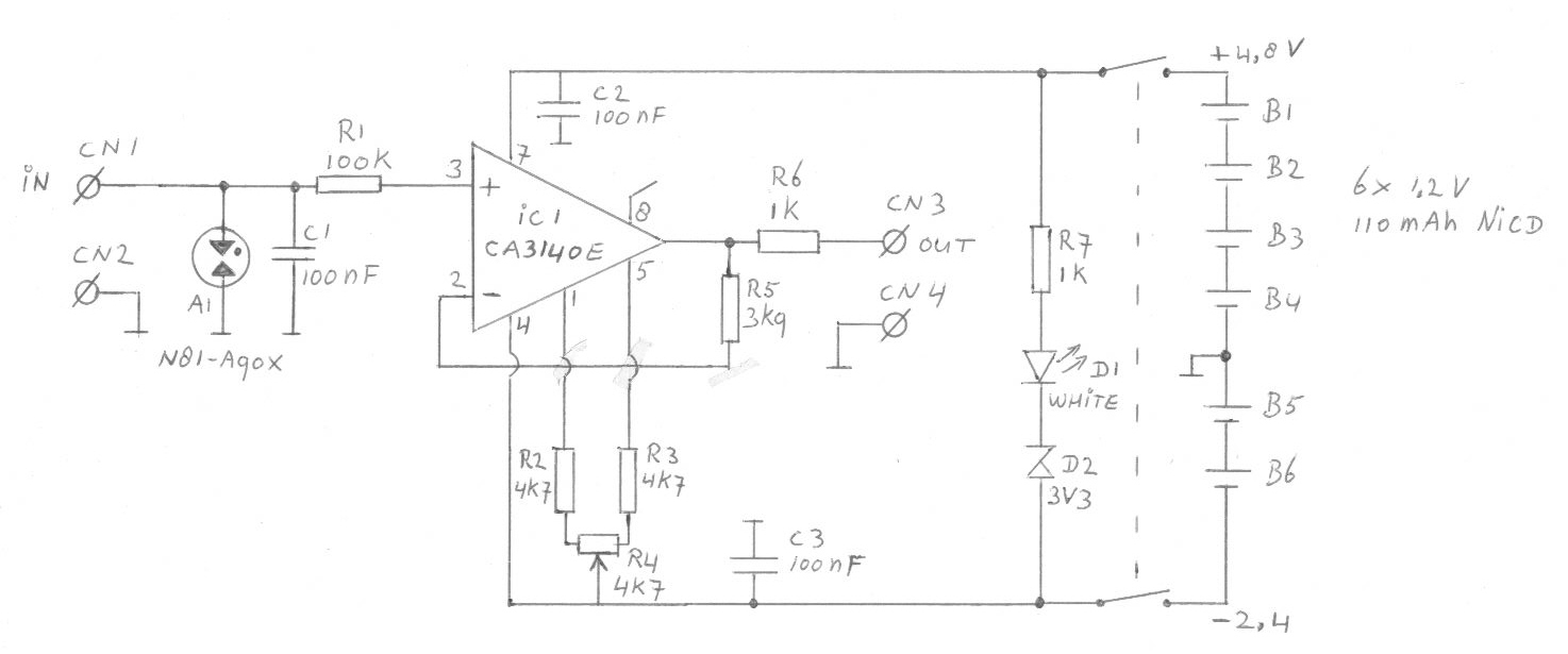
Another cause of voltage drift is the input current of IC1, which slowly charges capacitor C1. This effect is particularly noticeable when the output voltage is approximately 0 volts.
The circuit in question involves an integrated circuit (IC1) whose input current...
Circuit to Measure Power Supply Voltages
To obtain the power supply graphs on the previous page, the circuit is designed to independently monitor the power sources with the addition of a few resistors. Diode D3 allows the solar panel voltage to charge the batteries, while the...
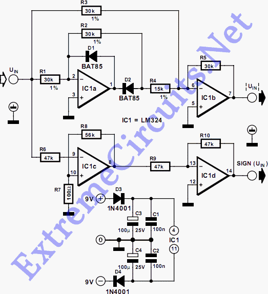
Absolute-Value Meter With Polarity Detector
This circuit separates an input voltage signal into its components: (1) the absolute value and (2) the polarity or 'sign' (+ or -). It is designed to handle direct current (DC) signals.
The circuit operates by utilizing operational amplifiers (op-amps) to...