
Room Noise Detector

This circuit utilizes a single LED to indicate ambient noise levels at three predefined thresholds: 50 dB, 70 dB, and 85 dB. The core of the circuit comprises two operational amplifiers (op-amps) configured as a gain stage to amplify the audio signals captured by a miniature electret microphone. The electret microphone converts sound waves into electrical signals, which are then processed by the op-amps to ensure that even low-level sounds can be effectively monitored.
The circuit is designed with a switch, SW1, which has four positions. In the first position, the circuit is powered off, conserving energy. In the second, third, and fourth positions, the circuit is powered on, and the sensitivity threshold is set to 85 dB, 70 dB, and 50 dB respectively. This allows users to select the desired noise level for monitoring, making it versatile for different environments.
The LED serves as a visual indicator, flashing when the ambient noise exceeds the selected threshold. The current consumption of the circuit is notably low, drawing less than 1 mA when the LED is off, and between 12 to 15 mA when the LED is illuminated steadily. This efficiency makes the circuit suitable for prolonged use in various settings, including bedrooms where monitoring for excessive noise levels is critical for maintaining a peaceful environment.
To implement this circuit, it is recommended to place the enclosure containing the circuit in the area where noise levels are to be monitored. The design ensures that the 50 dB setting is particularly useful for quiet environments like bedrooms, allowing for effective monitoring of sound levels that could disrupt sleep. Overall, this noise level monitoring circuit is a practical solution for detecting and signaling excessive noise in various settings.One LED monitors three levels: 50, 70 & 85 dB Useful to detect too noisy environments. This circuit is intended to signal, through a flashing LED, the exceeding of a fixed threshold in room noise, chosen from three fixed levels, namely 50, 70 & 85 dB. Two Op-amps provide the necessary circuit gain for sounds picked-up by a miniature electret microphone to drive a LED.
With SW1 in the first position the circuit is off. Second, third and fourth positions power the circuit and set the input sensitivity threshold to 85, 70 & 50 dB respectively. Current drawing is <1mA with LED off and 12-15mA when the LED is steady on. * Place the small box containing the circuit in the room where you intend to measure ambient noise. * The 50 dB setting is provided to monitor the noise in the bedroom 🔗 External reference
Related Circuits
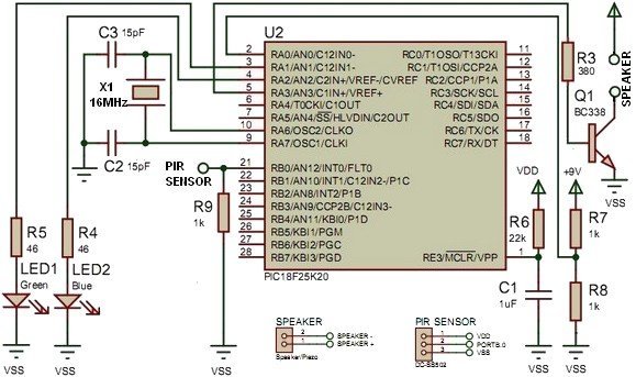
This project utilizes the PIC18F25K20 microcontroller to detect changes in a sensor's state and emit sound from a speaker or piezo buzzer. The microcontroller also monitors the battery voltage during startup. The algorithm is straightforward, employing an interrupt-on-change mechanism...

Portable devices such as video cameras, halogen floodlights, electrical irons, hand drills, grinders, and cutters are powered by connecting long 2- or 3-core cables to a mains plug. Prolonged use can subject the power cord wires to mechanical strain...
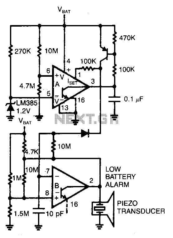
Comparator A detects when the supply voltage drops to 4 V and enables comparator B to drive a piezoelectric alarm. More: Is: 6V at 45μA, Is: 3.8V at 1μA, f: 3kHz The circuit utilizes two comparators to monitor supply voltage...

The circuit can be used to determine whether an input signal falls within a specific frequency range. The device comprises three integrated circuits (ICs), including a dual monostable multivibrator and two dual D-type flip-flops. The signal whose frequency is...
Using only a single transistor and a few passive components, a fairly sensitive peak detector circuit can be built. This peak detector circuit is suitable for various applications. The peak detector circuit utilizes a single transistor, typically configured in a...
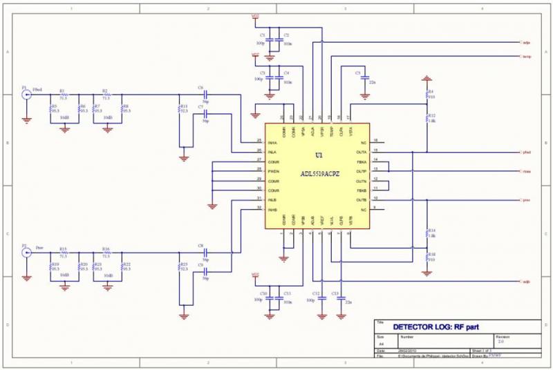
The ADL5519 is particularly focused on bandwidth, specified up to 8 GHz, though it remains usable at 10 GHz with reduced dynamic range. It features two channels, allowing for the measurement of power transmitted to the antenna and the...