
Sensitive Continuity Checker

The continuity checker circuit utilizes the LM339 quad comparator, which is known for its reliability and precision in analog signal processing. The circuit configuration includes resistors R1 and R3, which form a voltage divider that sets a reference voltage for the comparator. The unknown resistance, Rx, is connected across the test leads, allowing the circuit to measure continuity by comparing the voltage drop across Rx with the reference voltage.
When the circuit is powered on, U1 compares the voltage from the bridge circuit against the reference voltage established by R1. If the voltage drop across Rx indicates that the resistance is below the set threshold, the output of the comparator goes low, triggering the open-collector output. This action activates the LED indicator, providing a visual signal that continuity exists. Simultaneously, the piezo buzzer B2 is energized, producing an audible alert to signal the user.
The design effectively mitigates the effects of inductive components and low-resistance devices, ensuring that false positives are minimized. The use of an open-collector output allows for flexibility in connecting multiple indicators or alarms if needed.
In summary, this continuity checker circuit is a practical tool for testing electrical connections, leveraging the capabilities of the LM339 comparator to provide reliable continuity indications through both visual and audible signals. The careful selection of components and their arrangement in the circuit ensures accurate performance across a range of applications. This continuity checker (built around an LM339 quad comparator with open-collector outputs) eliminates false r eadings because of coils or low-resistance devices in a circuit. Ul is a comparator that acts as a sensing amplifier for the bridge circuit (Rl and Dl, R3 and the unknown resistance, Rx that is connected across the test leads. When iTis less than this predetermined value (by the setting of Rl), the LED lights and B21 sounds.
Related Circuits
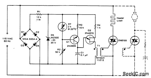
Triac temperature-sensitive heater control. This circuit can be modified to control a motor with a constant load. While the circuit is designed for heating applications, it can also be adapted for cooling by interchanging RT and R2 (courtesy of...
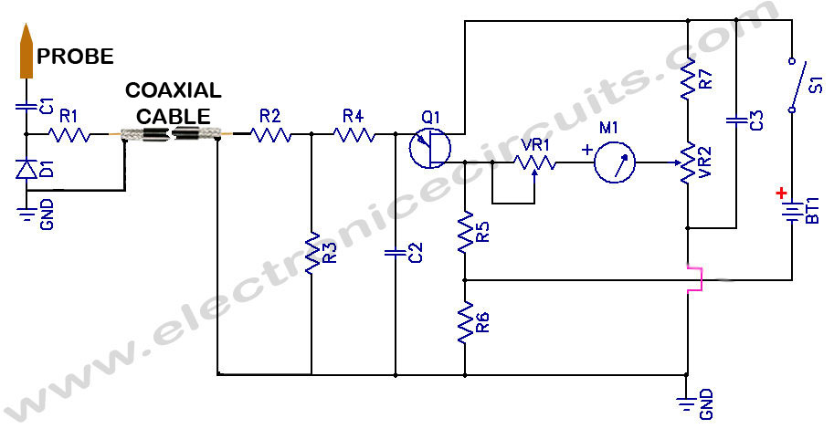
Sensitive RF Voltmeter Probe Circuit. This circuit measures RF voltages beyond 200 MHz and up to approximately 5V. The sensitive RF voltmeter probe circuit is designed to accurately measure radio frequency (RF) voltages in the range exceeding 200 MHz,...
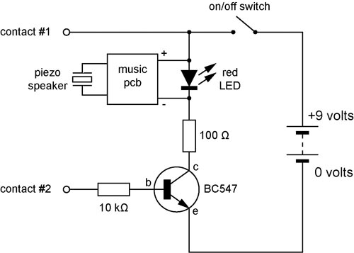
A continuity tester is useful for verifying that there is a conductive path between two points. This circuit offers the advantage of being highly sensitive, providing both visual and audible indications of continuity. An audible tester is particularly beneficial...
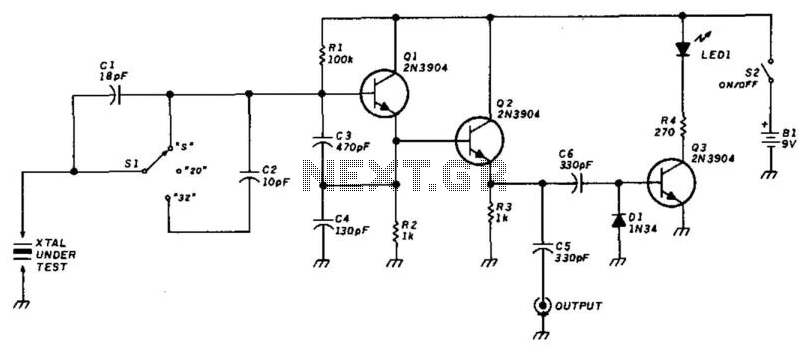
This circuit utilizes a Colpitts oscillator (Q1) paired with a buffer amplifier (Q2) to facilitate crystal testing. SI allows for the selection of three load conditions: series (S), 20 pF, and 32 pF. It is essential to keep the...
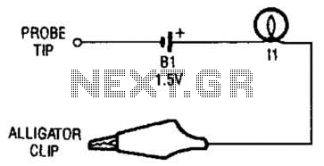
The continuity tester consists of a battery and a lamp connected in series, with one end of the circuit terminated with an alligator clip and the other end connected to the probe tip. The continuity tester is a fundamental...

This tester is designed to verify integrated circuit (IC) printed circuit boards. It incorporates two 4 kΩ resistors along with transistors that inhibit current flow through the operational amplifier until the probe circuit is fully established. Additionally, a zener...