
Servo motor Tester with PIC12F675

The described servo tester is a compact electronic device designed to evaluate the functionality of various modern servos. The core of the circuit is based on the PIC12F675 microcontroller, which is responsible for generating the control signals necessary for servo operation. This microcontroller features an internal timer that provides a precise timing mechanism, allowing for consistent frame durations of 20 milliseconds, which is the standard for most servos.
The circuit includes two pushbuttons: CENTRE and SWEEP. The CENTRE button allows the user to position the servo at its neutral point. When this button is pressed, the microcontroller interprets the command and sends a signal to the servo to move to its center position. The user can then adjust the potentiometer (R5, a 5K variable resistor) to fine-tune the servo's position within a specific range.
The SWEEP button activates a sweeping function, which causes the servo to move back and forth across its entire range of motion. The rate at which this sweeping occurs is adjustable via the potentiometer, allowing the user to set the speed of the motion according to their requirements. This feature is particularly useful for testing the responsiveness and range of motion of the servo.
The circuit design incorporates various passive components to ensure stable operation. Resistors R1 (1K), R2 (10K), R3 (82R), and R4 (10K) are used for biasing and signal conditioning. Capacitors C1 (27pF), C2 (27pF), and C3 (100nF) are employed for decoupling and filtering purposes, ensuring that the microcontroller operates reliably without interference from noise.
A 4.7V zener diode (D1) is included in the design to provide voltage regulation, protecting the circuit from voltage spikes and ensuring stable operation. The 10MHz crystal (Q1) is utilized to provide a precise clock signal for the microcontroller, which is essential for accurate timing and operation of the servo control signals.
This servo tester serves as an essential tool for hobbyists and engineers alike, allowing for comprehensive testing and calibration of servos in various applications. Its simple yet effective design makes it accessible for users with varying levels of experience in electronics.This is a simple servo tester which will comprehensively test the capabilities of almost any modern servo. It has two pushbuttons, CENTRE and SWEEP and a potentiometer which works as follows: CENTRE Does exactly that, centers the servo, afterwards the potentiometer determines position.
SWEEP Sweeps the servo back and forth at a rate determined by the potentiometer setting. The PIC uses its internal timer to set up a constant frame duration of 20ms and the on/off ratio is set by the user. Parts List R1 = 1K R2 = 10K R3 = 82R R4 = 10K R5 = 5K potentiometer C1 = 27pF C2 = 27pF C3 = 100nF D1 = 4,7V zener diode Q1 = 10MHz crytal IC1 = PIC12F675 🔗 External reference
Related Circuits

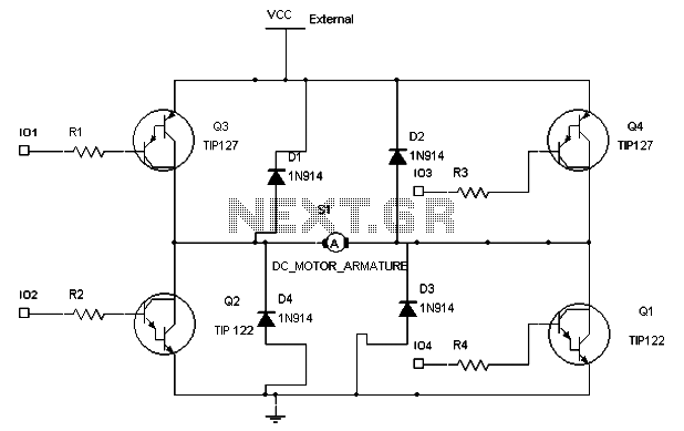
This is the power diagram for motor forward and reverse operation. To change the motor direction, one polarity must be altered, for example, changing R to S. For detailed information, please refer to the following. The described power diagram illustrates...

Tools that feature the equivalent of a professional, easy-to-use, cheaper, and, more importantly, safe for use. They are designed for checking and identifying AC voltages of 220 Volt or 120 Volt. The tools mentioned are essential for ensuring electrical safety...
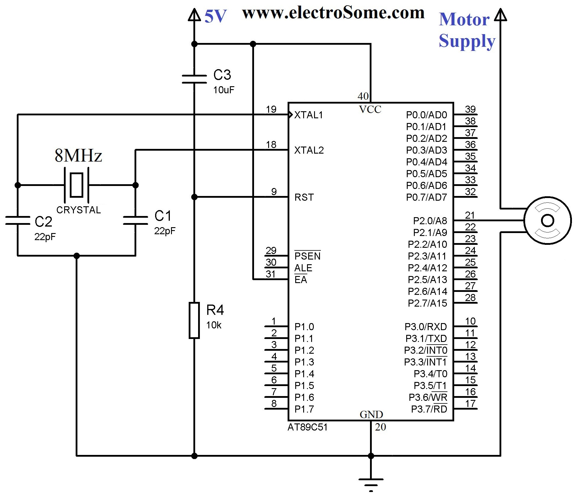
To maintain a constant speed of the motor under varying load conditions, a control application circuit is required. An H-Bridge circuit can be utilized to manage both the speed and direction of the motor. The accompanying diagram illustrates the...
A servo motor employs a servo mechanism, which is a closed-loop system that utilizes position feedback to accurately control the angular position of its shaft. Stepper motors, which operate as an open-loop system, can also achieve precise angular control,...
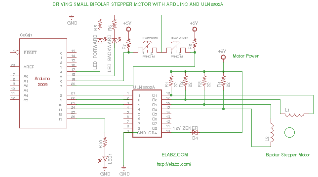
While preparing to disassemble several broken DVD-RW drives obtained from an eBay seller, the idea arose to create a testing platform for the bipolar stepper motors that would be salvaged from these drives. A collection of ULN2803AG Eight Darlington...
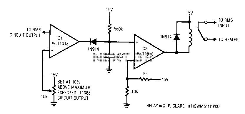
This circuit responds quickly enough to prevent damage from most overloads. Capacitor C1's input is connected to the output of the LT1088 servo circuit. If the LT1088 circuit's output exceeds the threshold at C1's other input, C1 trips, discharging...