
servo speed tester

The described circuit functions as a basic servo motor tester, primarily aimed at evaluating the operational speed and position of a servo motor. The circuit employs a 555 timer configured in astable mode, generating a pulse-width modulation (PWM) signal that controls the servo's movement.
Key components include a potentiometer, which serves as a variable resistor, allowing for fine adjustments to the voltage supplied to the servo. By varying the resistance, the effective voltage and current reaching the servo can be altered, thus controlling the speed at which the servo rotates. The use of a 4.5V power supply is suitable for most standard servos, ensuring safe operation without exceeding the motor's voltage ratings.
Additionally, the circuit incorporates two push buttons that facilitate manual control over the servo's direction. One button is designated for clockwise rotation, while the other is for counterclockwise rotation. When pressed, these buttons send a signal to the 555 timer, which then adjusts the duty cycle of the PWM signal, effectively changing the rotation direction of the servo.
This simple yet effective circuit serves as an educational tool for understanding servo mechanics, PWM control, and the operation of the 555 timer in practical applications. It is suitable for hobbyists and beginners in electronics, providing hands-on experience with servo motors and basic circuit design.This is probably the simplest Circuit to test a Servo, This circuit tests the speed of servo. Here we use potentiometer to controll the speed of the servo. By applying very less voltage like 4. 5V and reducing the pot value, you can also adjust the position of the servo! Check this Circuit which uses push switches to run a servo in Clock-wise and a nti Clock-wise directions using 555 timer 🔗 External reference
Related Circuits
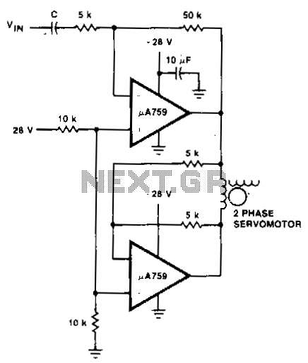
This motor driver circuit utilizes a p.A759 power amplifier to drive a two-phase servomotor. The motor driver circuit is designed to efficiently control a two-phase servomotor, leveraging the capabilities of the p.A759 power amplifier. This amplifier is specifically chosen for...
This document outlines the theory behind a high-speed control scheme for an LED display screen circuit. The circuit utilizes the MCS51 series microcontroller to manage the LED display. A 62512 random access memory (RAM) is employed for data storage,...
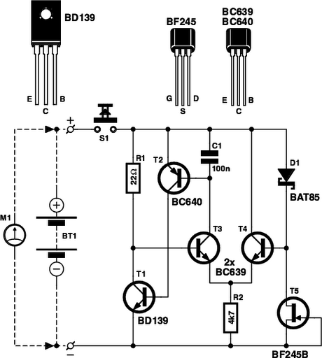
Is the battery empty, or is there something wrong with the device? This question can be challenging when a battery-powered device, such as a Walkman, appears to be non-functional upon switching it on. Before seeking professional servicing, the initial...

The circuit is designed to fit snugly, eliminating the need for adhesive. It is recommended to test the fit multiple times, making incremental adjustments until a snug but movable fit is achieved. The entire circuit should be placed inside...
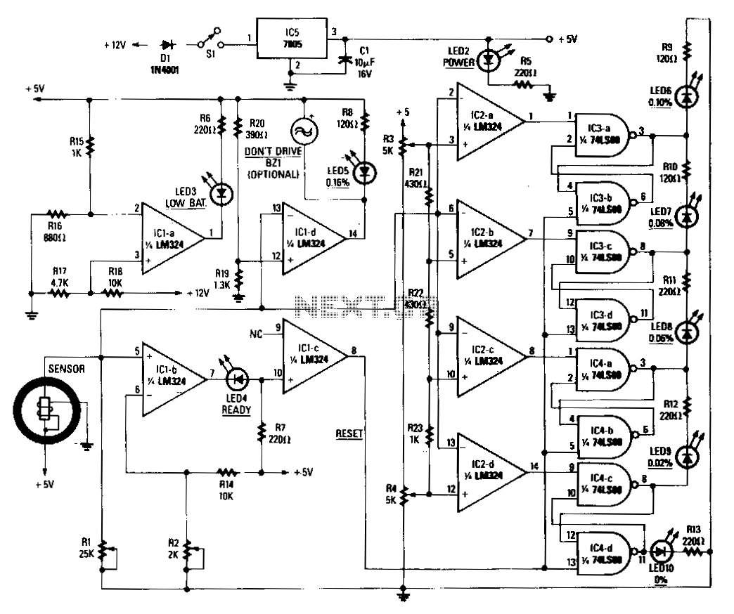
When power is applied to the circuit, the heater coil in the sensor is energized by the 5-V output of IC5, a 7805 voltage regulator. Breathing into the sensor with alcohol on one's breath will lower the sensor's resistance;...

Q1 functions as a Colpitts crystal oscillator. If the crystal being tested is operational, the RF signal is rectified by diodes D1 and D2, which activates Q2 and illuminates indicator LED2. Additionally, LED1 serves as a power indicator. The circuit...