
Crystal Tester Circuit

The circuit utilizes a Colpitts oscillator configuration, which is known for its stability and simplicity in generating high-frequency signals. Q1 is typically a transistor or an operational amplifier configured to create the necessary oscillation. The oscillation frequency is determined by the crystal under test, which is connected to the feedback network of the oscillator.
When the crystal is functional, it resonates at its designated frequency, generating an RF signal. This signal is then passed through rectifying diodes D1 and D2, which convert the alternating current (AC) RF signal into a direct current (DC) signal. The rectification process is crucial for powering subsequent components in the circuit.
The rectified signal is used to bias transistor Q2. When the voltage across Q2 reaches a certain threshold, it turns on, allowing current to flow through to LED2. This LED serves as an operational indicator, signaling that the crystal is functioning correctly by lighting up when Q2 is activated.
LED1 is included in the circuit as a power indicator, providing a visual cue that the circuit is powered and operational. Both LEDs are typically low-current devices, ensuring minimal power consumption while providing essential feedback to the user regarding the status of the circuit.
Overall, this circuit design exemplifies a straightforward method for testing crystal oscillators, integrating visual indicators to enhance usability and feedback for users. Ql acts as a Colpitis crystal oscillator, and if the crystal under test is operational, the RF signal is rectified by D1 and D2, turning on Q2 and lighting indicator LED2. LED1 is a power indicator.
Related Circuits
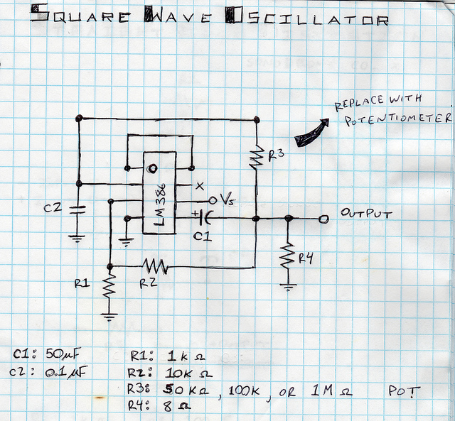
This is a square wave oscillator (digital, similar to 8-bit music). It is based on the LM386 amplifier integrated circuit, which is also the foundation for the mini guitar amplifier. The design includes a simple power switch connected to...
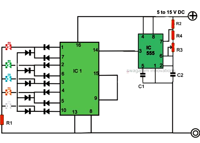
An LED light chaser circuit is an electronic configuration designed to illuminate a group of LEDs in a predetermined sequence. A commonly used integrated circuit (IC) for creating this type of LED sequencer circuit is the 4017. This IC...
Today, it is no longer necessary to use discrete components for constructing oscillators. Many manufacturers now offer ready-made voltage-controlled oscillator (VCO) integrated circuits (ICs) that require only a few external components to determine the frequency. An example of such...
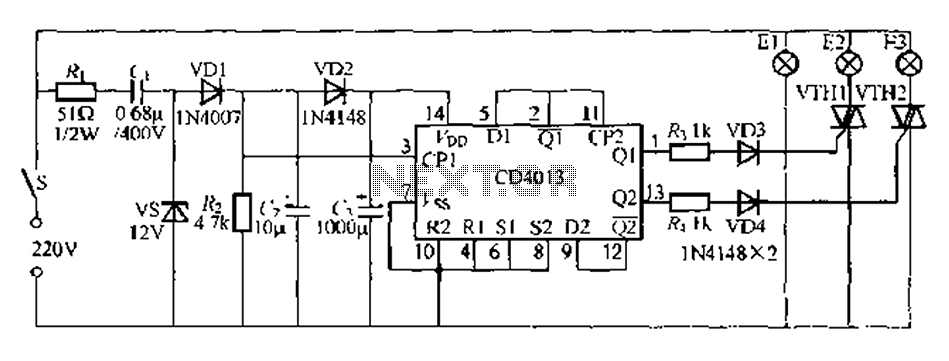
Figure 296 illustrates a control circuit that utilizes a switch (S) to manage three lamps (E1, E2, and E3) in a lighting system, suitable for controlling a chandelier in a living room. When the switch is off, all lights...
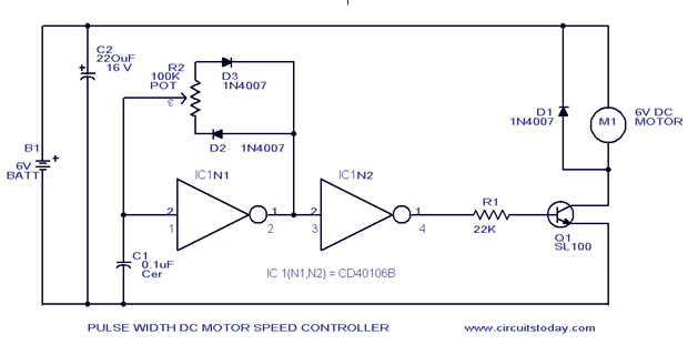
A simple PWM motor speed control circuit with a diagram and schematic for low power DC motors. This easy-to-make PWM DC motor controller is created using the IC CD40106B. The PWM (Pulse Width Modulation) motor speed control circuit utilizes the...
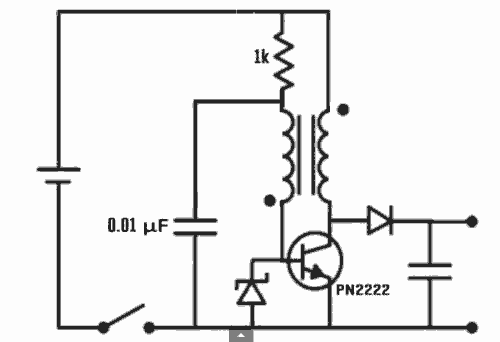
Excellent Joule thief circuit idea! The Joule Thief is a simple yet effective circuit designed to extract usable voltage from low-voltage power sources, such as depleted batteries. This circuit operates on the principle of boosting voltage through the use...