
Seven-7-Segment Counter Circuit with LED Display-Diagram and Schematic

The seven-segment counter circuit utilizes the CD 4033 integrated circuit, which is a BCD (Binary-Coded Decimal) counter. This IC is capable of counting from 0 to 9 and can directly drive a seven-segment display, converting the binary output into a human-readable decimal format. The 555 Timer IC is configured in astable mode to generate a continuous clock pulse, which drives the counting process.
The circuit begins with the 555 Timer, where resistors and capacitors are chosen to set the desired frequency of oscillation. The output of the 555 Timer provides a square wave signal that serves as the clock input for the CD 4033. The frequency of this clock signal determines the speed at which the counter increments.
The CD 4033 has several pins dedicated to output, which correspond to the decimal digits. When the clock pulse is received, the counter increments its count by one with each pulse. The output pins of the CD 4033 are connected to the inputs of the seven-segment display (LT 543), which lights up the appropriate segments to represent the current count visually.
To ensure proper operation, the circuit may include additional components such as pull-up resistors or decoupling capacitors to stabilize the power supply and prevent noise from affecting the performance. The design allows for straightforward implementation and is suitable for educational purposes or as a simple counting device in various applications.A simple seven/7 segment counter circuit with an LED display. This counter circuit diagram is designed using IC CD 4033 as counter,555 Timer IC and seven segment LED Display LT 543.. 🔗 External reference
Related Circuits
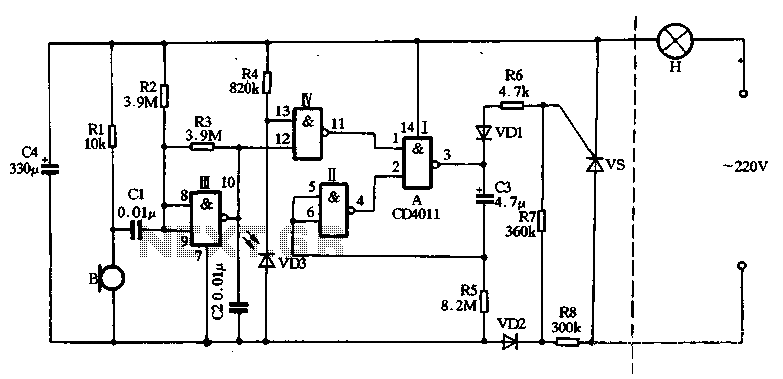
The main circuit utilizes a two-input NAND gate composed of four digital integrated circuits. This includes a NAND gate microphone amplifier circuit, a light control mechanism using an "AND gate," and a monostable delay control circuit formed by NAND...
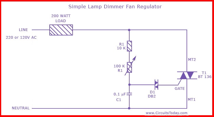
This is the circuit diagram of the simplest lamp dimmer or fan regulator. The circuit is based on the principle of power control using a Triac. The circuit operates by varying the firing angle of the Triac, which is...
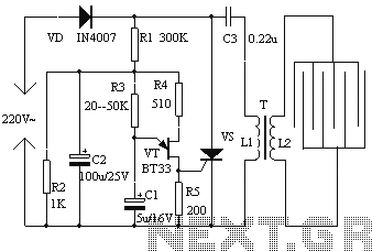
The electronic fly disinfestation system is a simple and effective device designed to eliminate flies using electrical means. The apparatus, as depicted in Figure 1, operates on 220V mains power supplied directly through a rectifier. It utilizes a relaxation...
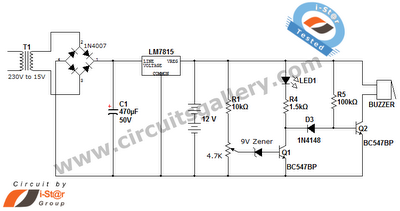
This is a straightforward 12V rechargeable smart battery charger circuit. It can be utilized as a charger for car batteries, inverter batteries, emergency light batteries, and more. An automatic indicator alarm circuit accompanies this battery charger schematic. The primary...
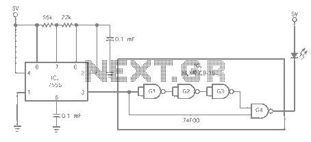
The entire series of TTL monostable multivibrators lacks sufficient speed, prompting the need for an ECL voltage swing that accommodates a wide range of small power requirements. This necessitates the use of F series circuits, which offer fast transition...
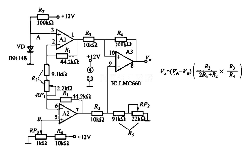
A diode IN4148 temperature circuit is presented. The circuit operates within a temperature range of -25 to 125 degrees Celsius, with an accuracy of 0.5. The core components of the operational amplifier circuit consist of four LMC660 amplifiers. It...