
SH Hall opened with a double silicon output interface circuit

The SH Hall sensor circuit is designed to provide a dual silicon output interface, which enables enhanced signal processing capabilities. This circuit typically integrates a Hall effect sensor that detects magnetic fields and converts them into an electrical signal. The dual output feature allows for simultaneous monitoring or interfacing with multiple systems or components, improving versatility in applications such as motor control, position sensing, and proximity detection.
In the schematic, the Hall effect sensor is connected to a power supply, often a regulated voltage source, which powers the sensor. The output pins of the Hall sensor are configured to provide two separate signals, which can be either analog or digital, depending on the specific application requirements. The outputs may be interfaced with microcontrollers or other digital processing units, allowing for further manipulation and analysis of the sensor data.
Additional components may include resistors for signal conditioning, capacitors for noise filtering, and possibly operational amplifiers to enhance the output signals. The circuit may also incorporate protection diodes to safeguard against reverse polarity or voltage spikes, ensuring reliable operation in various environments.
The layout of the circuit should be designed to minimize electromagnetic interference (EMI) and maintain signal integrity, especially when the circuit is used in environments with strong magnetic fields or electrical noise. Proper grounding and shielding techniques are essential to achieve optimal performance and accuracy in the sensor's readings.
Overall, the SH Hall sensor circuit with a double silicon output interface is a robust solution for applications requiring precise magnetic field detection and processing, providing flexibility and reliability in electronic designs.SH Hall opened with a double silicon output interface circuit
Related Circuits
The controller for the Hybrid Power Plant (HPP) is represented in a block diagram format. It consists of 440 Wp photovoltaic modules, a 1 kW wind turbine, and a 5 kW diesel engine as a backup power source. The...
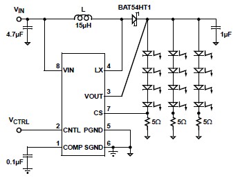
A simple white LED driver schematic can be created using the EL7513 constant current boost regulator, which is specifically designed for driving white LEDs. This driver can manage 4 LEDs in series or up to 12 LEDs in a...
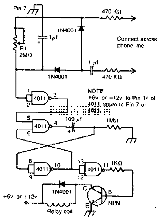
By cross-connecting the telephone ringing circuit, when the phone rings, the circuit activates the relay. It utilizes a delay in contact to drive various devices such as bells, sirens, buzzers, or lights. The telephone ringing circuit is designed to detect...
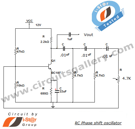
This section introduces a transistor oscillator circuit known as the RC Phase Shift Oscillator. An oscillator is an electronic circuit that functions as a sine wave generator, requiring only a DC power supply. It is commonly used in variable...
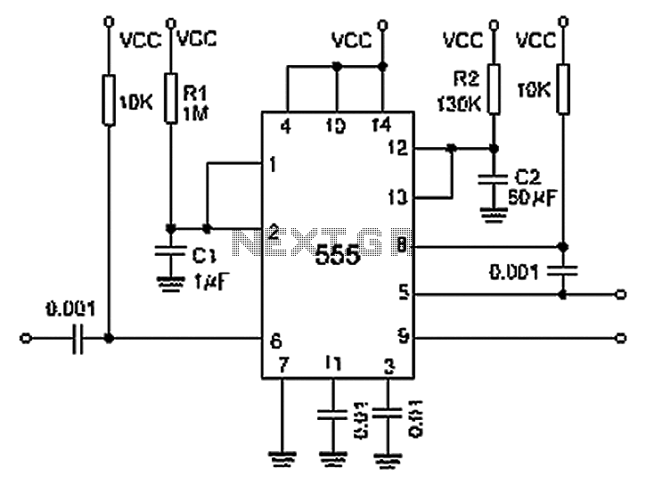
A 0.001 F coupling capacitor connects the output of the first half of a 556 timer to the input of the second half, providing an individual delay that equals the total delay. The 6-foot ground can immediately activate the...
The circuit utilizes an infrared (IR) receiver chip to capture IR signals from a remote control. This chip features a bandpass filter and a demodulator, resulting in a logic-level output. The controller section is based on a standard 8051...