
Telephone relay circuit

The telephone ringing circuit is designed to detect the ringing signal from a telephone line and use this signal to control a relay. The relay acts as a switch that can activate other devices, providing an alert or notification when a call is incoming. The circuit typically includes a resistor-capacitor (RC) delay network that introduces a time delay before the relay is energized. This delay allows for a smooth transition and prevents false triggering due to transient signals.
In the schematic, the telephone line is connected to a detection circuit that identifies the ringing voltage, which is typically around 90 volts AC at 20 Hz. This detection circuit may consist of a transformer to step down the voltage and rectify it to a suitable level for triggering the relay. The relay contacts are rated to handle the load of the connected devices, which can include various audible or visual alert systems such as bells, sirens, buzzers, or lights.
Furthermore, the circuit may incorporate additional components such as diodes for flyback protection, ensuring that voltage spikes generated when the relay coil is de-energized do not damage the circuit. An LED indicator can also be included to provide a visual indication of the circuit's operation, illuminating when the relay is active.
Overall, this telephone ringing circuit is a versatile solution for alerting individuals of incoming calls, enhancing communication in various environments, including homes, offices, and industrial settings. Proper design and component selection are crucial for ensuring reliable performance and longevity of the circuit. By cross-connect telephone ringing circuit, when the phone rang, the circuit closes the relay. It uses the delay in contact, thus to drive any bells, sirens, buzzers or lights.
Related Circuits
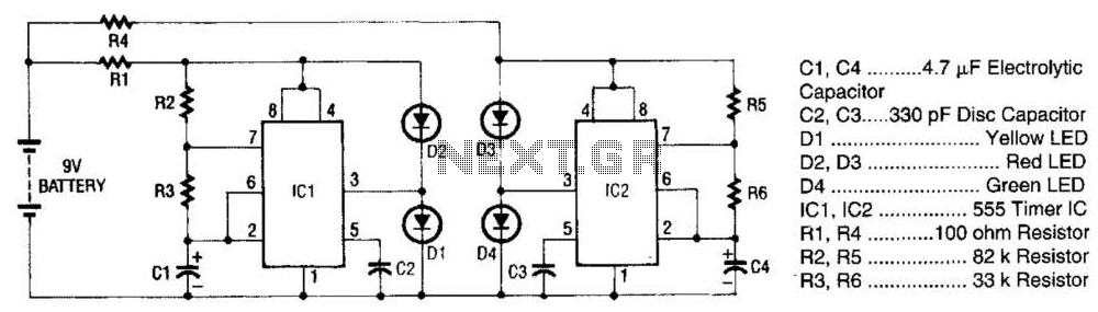
The super LED flasher consists of two complete LED flasher circuits integrated onto a single circuit board. The first LED flasher is comprised of IC1 and LEDs D1 and D2. IC1 is a 555 timer IC configured as an...
This 555 timer circuit below toggles a relay when a button is pressed. Pins 2 and 6, the threshold and trigger inputs, are held at 1/2 the supply voltage by the two 10K resistors. When the output is high,...
This tremolo effect circuit utilizes the XR2206 and TCA730 integrated circuits, designed for electronic balance and volume regulation with frequency correction. The circuit is beneficial for stereo channels and can simulate the Lesley effect, also known as the rotating...
The circuit utilizes a thermistor and three sections of a LM3900 quad operational amplifier (op amp) integrated circuit. When the temperature decreases to 36°F, an LED indicator flashes approximately once per second. As the temperature continues to drop to...
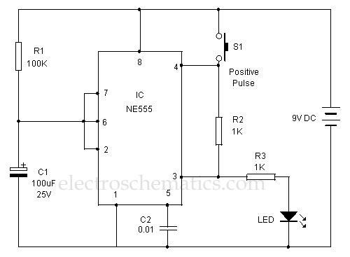
This 555 timer is designed uniquely to provide a positive output through control over its reset pin. Typically, the 555 timer IC is triggered by applying a negative voltage. The 555 timer is a versatile integrated circuit widely used in...

Using a power MOSFET, this amplifier can achieve a 2-W handheld radio power level, increasing it to approximately 10 W on the 2-meter band. A transmission-line RF switch is employed for transmit/receive (T/R) switching. The described amplifier utilizes a power...