
Side tone coupling circuit diagram

The receiver sidetone circuit is an essential component in telephone systems, ensuring that users receive auditory feedback of their own voice during conversations. This feedback is crucial for maintaining natural communication, as it helps users modulate their speaking volume and prevents them from feeling isolated from the conversation.
In the circuit, inductors L1 and L2 are strategically designed with an unbalanced turns ratio to create a differential in the magnetic fields they generate. This differential is critical for inducing a controlled amount of sidetone into inductor L3. The resistor R plays a significant role in this process; by adjusting its value, the circuit can be fine-tuned to achieve the desired level of sidetone without matching the line impedance, which could lead to undesirable feedback or distortion.
The output from inductor L3 is then fed back into the receiver, allowing the user to hear their own voice. The level of sidetone must be carefully calibrated; too much sidetone can cause confusion and lead to lower speaking volumes, while too little can result in the user believing the line is dead, prompting them to raise their voice unnecessarily.
Overall, the design of the sidetone coupling circuit is a delicate balance of inductive coupling, resistance, and impedance matching, all aimed at enhancing the user experience in telephone communications.Side tone coupling:In telephones, it is the hearing of one`s voice in the receiver when one speaks. Too muchside tonemake people speak lower and can cause feedback. Too littleside toneand people may think the phone is not working or may shout. Figure This is a simplified schematic diagram of a receiver sidetone circuit. Because curren t will not flow through a balanced circuit, the turns ratio of inductors L1 and L2 is unbalanced by a predetermined amount and the value of resistor R is changed so as not to match the line impedance. This way, a controlled amount of signal can be induced into L3 to be used as receiver sidetone. 🔗 External reference
Related Circuits
This custom mod gives your computer the personality of KITT, the computerized car from Knight Rider TV fame. The project is a light display which imitates the dot in KITT's hood. It looks like the scanning eye of the...
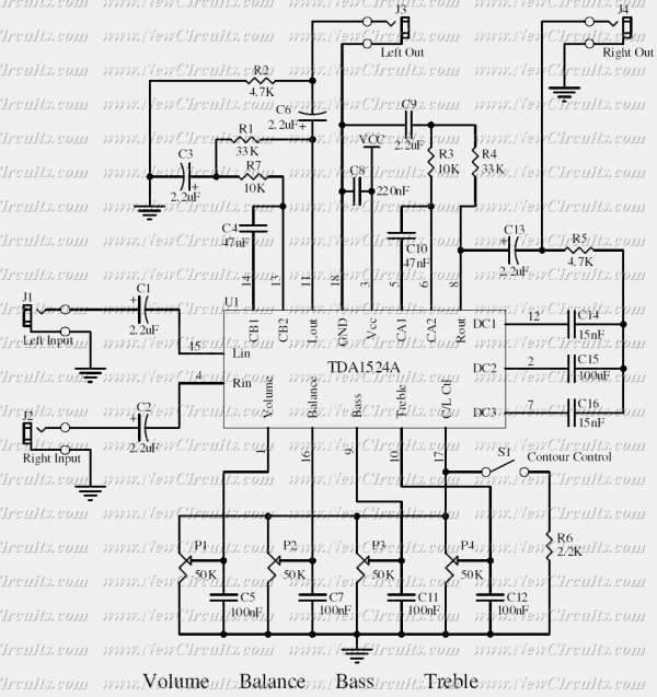
This simple tone control can be used in many audio applications. It can be added to amplifiers, used as a stand-alone control module, or even built into new and exciting instruments. Its one IC construction makes it a very...
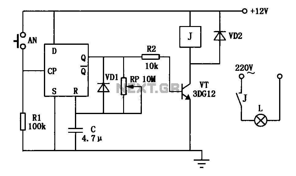
An exposure timer circuit is illustrated using D flip-flops, allowing for timing adjustments between 1 to 30 seconds. The D flip-flop circuit is connected to a one-shot timer. When exposure is required, pressing button AN generates a pulse that...
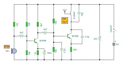
This is a mini FM transmitter circuit that utilizes two transistors. The audio sensitivity is notably high when paired with an ECM type microphone. The transmitter operates using a Hartley oscillator configuration. Typically, the capacitor in the tank circuit...
Parts List The circuit was specifically designed for shop window animation as it utilizes a capacitive sensor that is activated by a touch control system. The circuit is intended for enhancing visual displays in retail environments by creating dynamic animations...
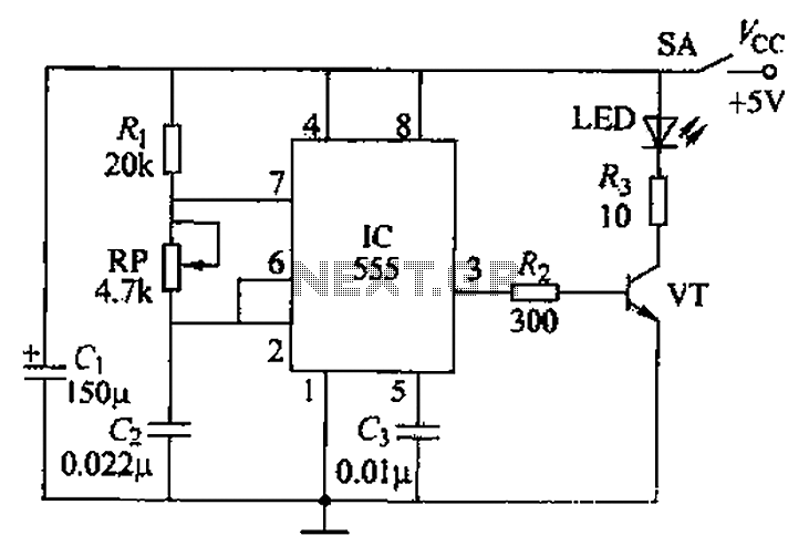
The circuit utilizes a 555 timer integrated circuit along with a transistor (VT) and several external components to create a multivibrator circuit. The charge and discharge time constants, Ti and T2, are defined, where Ti is approximately 0.7 times...