
Signal Detecting Auto Power-On Unit

To create a circuit that enables the activation of a sub-woofer or similar audio equipment via a signal, a simple relay-based design can be employed. The circuit operates by detecting a low-voltage control signal, which can be generated from various sources, such as a line-level audio output or a dedicated switch.
The core of the circuit consists of a relay, which acts as an electrically operated switch. When the control signal is applied, it energizes the relay coil, closing the normally open (NO) contacts and allowing the main power to flow to the sub-woofer. This approach provides a safe and effective means to control high-power audio equipment without directly interfacing low-voltage control signals with high-voltage circuits.
For the control signal, a transistor can be used to amplify the input signal if necessary. A resistor can be placed in series with the base of the transistor to limit current and prevent damage. Additionally, a diode should be connected in parallel with the relay coil to protect the circuit from back EMF generated when the relay is de-energized.
Power supply considerations should also be taken into account. The relay should be rated for the voltage and current of the audio equipment being controlled. A suitable power supply must be provided to ensure reliable operation of both the relay and the control circuit.
This relay-based activation circuit can be easily integrated into existing audio setups, providing a practical solution for remotely turning on sub-woofers or other audio devices without the need for complex modifications or additional equipment.How many times have you wished that there was a simple way to turn on that sub-woofer or some other piece of audio equipment, simply by sending it a signal? This ability is fairly common in commercial subs and some other gear, but there seems to be a complete absence of circuits on the net, and they seem completely unavailable as an add-on device.
🔗 External reference
Related Circuits
This project is one for the experimenter, but as shown will work extremely well. The sensing circuit can be made so sensitive that a load of only 2.5mA is enough for the circuit to detect, and disconnect the charger....
This is a PIN diode-based RF signal attenuator circuit that operates with input frequencies ranging from 1 MHz to 500 MHz. PIN diodes are among the most commonly used components in RF applications. The RF signal attenuator circuit utilizing PIN...
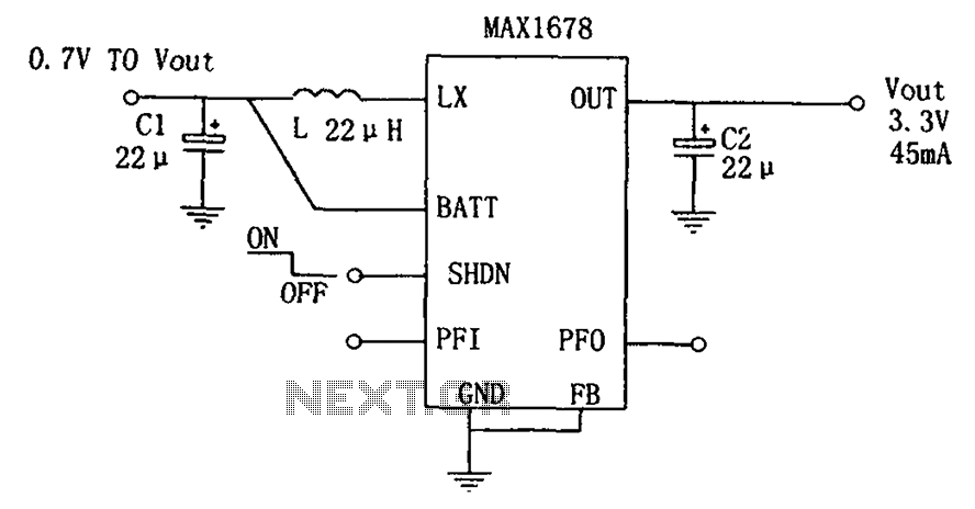
As depicted in the figure, this circuit is suitable for high-efficiency single-cell battery power boosting. It comprises a MAX1678 integrated circuit and three external components. The MAX1678 is designed for low-power applications and features an ultra-small 8-pin MAX package....
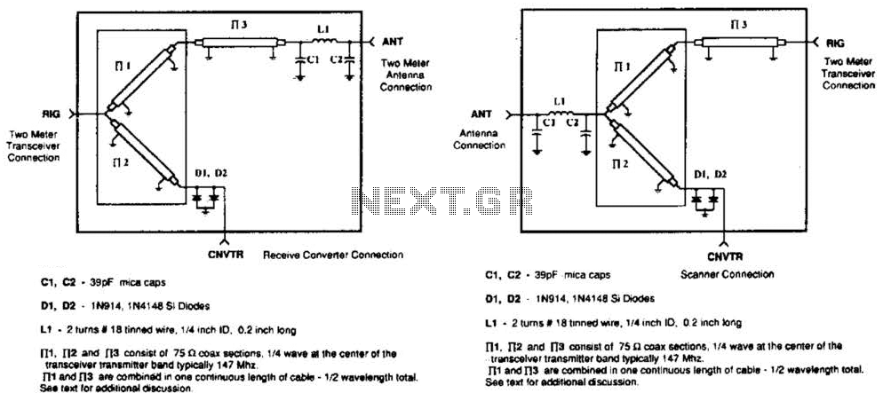
A pair of diodes and a quarter-wave transmission line are utilized as an automatic TR switch. D1 and D2 conduct during transmit periods, short-circuiting the scanner input. In this mode, the quarter-wave line appears as an open circuit. In...

The LT1007 is capable of providing excitation current directly to bias the 350-0 bridge at 5 V. With only 5 V across the bridge, as opposed to the usual 10 V, total power dissipation and bridge warm-up drift is...
The DW L11 capacitor steps down voltage into the Jenru half crossing according to Yin electrical specifications. After receiving power at the bin CI SH output terminal, it regulates the voltage to liVI/r j, ensuring a right cut in...