
Signal Generator 20KHz

The function generator described operates within a frequency range up to 20 MHz, although practical usage has been observed to be effective up to 50 kHz. This device utilizes an integrated circuit (IC) that can generate various waveforms, typically sine, square, and triangle waves, essential for testing and development in electronic applications.
Two primary methods are employed for frequency control. The first method involves manual adjustment of the control voltage supplied to the IC. This method requires the user to interact with a control knob while monitoring the frequency output on a connected counter. However, this approach can be cumbersome, as the display updates occur only once per second, leading to potential inaccuracies during fine-tuning.
The second method enhances usability by automating the control process. In this configuration, the user sets the desired frequency using the control knob, and the circuit automatically adjusts the control voltage to the IC to achieve the target frequency. This is accomplished by calculating the required period for the desired frequency and utilizing a PIC (Programmable Interface Controller) to measure the pulse width of the output signal. The PIC then generates short correction pulses that are sent to an integrator circuit, which modulates the control voltage to stabilize the output frequency.
The integration of a PIC allows for a more responsive and accurate frequency adjustment, minimizing the need for manual intervention and streamlining the operation of the function generator. The inclusion of source, object, and schematic files indicates that the design may be open for further development, allowing users to modify or enhance the functionality of the circuit as needed.This fucntion gernerator IC is specified to work to 20 MHz. So far, this unit works nicely to 50KHz. Since I seldom need signals higher than that, it has taken up a happy home on my workbench and further development is iffy at best. There are two basic approaches to controlling the frequency in this type of device. One way is to adjust the voltage to the IC manually and then read out the frequency with a counter. The problem here is you need to fiddle around with the control knob and while waiting for the one-per-second updates on the display.
The other way is to set the display with the control knob and then have the circuit diddle the control voltage to the IC until it settles on that frequency. This is done by calculating the period for the target frequency and then using the PIC to read the pulse width.
It then sends short correction pulses to an integrator which controls the IC. For your edification and amusement here are the Souce, Object, and Schematic files. 🔗 External reference
Related Circuits
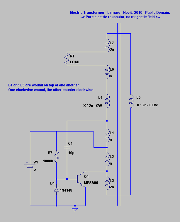
The principle involves a parasitic capacitance between coil windings that stores energy. By utilizing bifilar winding for the coil, a significantly larger voltage difference is achieved between adjacent windings, resulting in increased energy storage in these parasitic or self-capacitances....
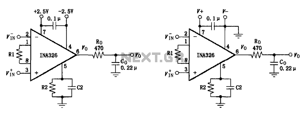
The basic connection circuit for the INA326/327 includes signals and power. A 0.1 µF capacitor is selected for power supply filtering and should be placed as close to the chip's supply pin as possible. Ro and Co serve as...
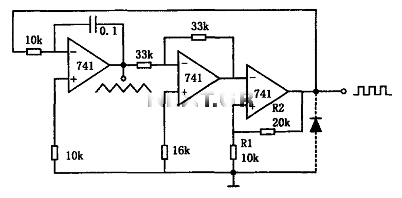
The circuit illustrated generates a variety of low-frequency waveforms, specifically triangle and square waves, simultaneously. It consists of several stages: the first stage is an integrator, followed by a gain stage with an inverter, and a comparator stage that...
This circuit is designed to detect microwave sources, such as microwave ovens, satellite communication devices, and mobile phones. It provides audio-visual indications upon detecting microwaves in the gigahertz band, which encompasses frequencies between 2 GHz and 300 GHz. Microwave...
The signal from a microphone is too weak for a standard line input. This low-noise DC-coupled microphone amplifier provides a solution for anyone who wants to connect a microphone to a high-fidelity installation. As shown in the schematic diagram,...
The I/O board incorporates 16-bit resolution voltage analog inputs and outputs, along with a 4-20mA current loop transmitter and receiver for microcontroller applications. The document discusses amplifier circuits and schematics, including a signal conditioning variable gain amplifier, analog filter,...