
Signal injectoh-tracer

The described circuit features a CMOS oscillator designed for generating a square wave signal with a specific frequency determined by the values of capacitor Cl and resistor R2. The output frequency is set to 1 kHz, making it suitable for various audio applications. The output voltage is regulated to 1 V through the voltage divider formed by resistors R3 and R4, ensuring compatibility with downstream components.
The operational behavior of the oscillator involves digital logic gates that typically function in a binary state. However, in this configuration, the gates are employed in a linear mode. This is achieved by incorporating negative feedback from the output back to the input, allowing the circuit to stabilize and operate similarly to an operational amplifier. This design choice enhances the linearity and fidelity of the output signal.
The positive ground configuration is particularly advantageous in audio applications, specifically at the earphone output stage. In traditional designs, one side of the earphone is connected to ground, which is often the negative terminal. By utilizing a positive ground, the circuit can drive the earphone more effectively. The inclusion of two N-channel transistors from the CD4001 in a parallel arrangement allows for increased current handling capability, resulting in enhanced audio volume output. This arrangement is beneficial for driving headphones or earphones, ensuring that the audio signal remains clear and powerful without distortion.
Overall, the combination of a CMOS oscillator with a positive ground configuration, along with the use of operational amplifier-like feedback, provides a robust solution for audio signal generation and amplification. The careful selection of component values and configurations ensures optimal performance in various electronic applications.The injector is a CMOS oscillator with period approximately equal to 1 x Cl x R2 seconds. The values are given for 1 kHz operation. Resistors R3 and R4 divide theoutput to 1 V; Whereas the oscillator employs the gates in their digital mode, the tracer used them in a linear fashion by applying negative feedback from output to input. They are used in much the same way as op amps. The circuit uses positive ground It offers an advantage at the earphone output because one side of the earphone must be connected to ground via the case. Use of a positive ground allows the phone to be driven by the two N-channel transistors inside the CD4001 which are arranged in parallel and are thus able to handle more current for better volume.
Related Circuits

The 3-wire interface to the AD7714 can be utilized with various microcontrollers, including microcontrollers and microprocessors. This 3-wire serial interface is particularly suitable for isolation systems, allowing the use of optical couplers. The interface circuit between the AD7714 and...
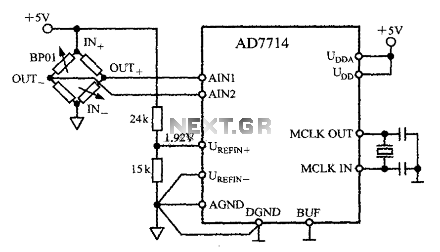
The AD7714 circuit consists of a pressure measurement system featuring the BP01 pressure sensor from Sensym. The BP01 is integrated into a bridge circuit, which produces a differential output voltage. When the sensor is subjected to its rated full-scale...
A 2001 Monte Carlo is experiencing electrical issues where only the lights are functioning. The radio, wipers, turn signals, and dash lights do not operate when the ignition key is turned. It has been suggested that the computer system...
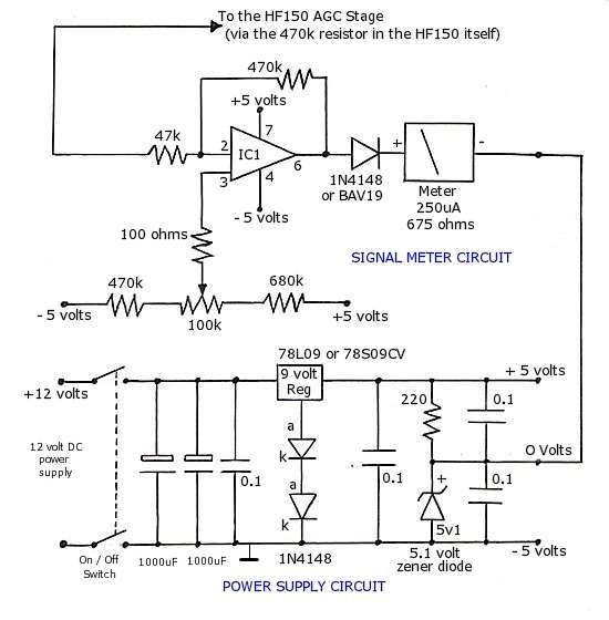
The operational amplifier (op-amp) used in the signal meter circuit is the TL061. The LF351 can also be used interchangeably, as it has the same pin layout. For those using a TL062 or similar models, the differing pin configurations...
Involvement is a modified version of the classic circuit of automatic level control signal used in tape recorders. The purchase price of the components (using TL072) does not exceed CZK 60 for a channel. For a range of entry...
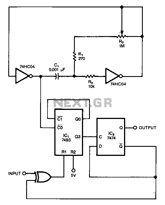
This circuit filters noise, such as glitches and contact bounce, from digital signals. It can be easily adjusted for a wide range of noise frequencies. The circuit's output changes state only if the input differs from the output long...