
5-channel low-power interface circuit programmable sensor signal processor AD7714 and MCS-51 series microcontroller

The AD7714 is a precision analog-to-digital converter (ADC) that communicates via a 3-wire serial interface, making it ideal for applications requiring isolation. This interface allows for the integration of optical couplers, which can enhance system safety by isolating high-voltage sections from sensitive microcontroller components. The 80C51 microcontroller, a widely used device in embedded systems, interfaces with the AD7714 using two of its GPIO pins, specifically P3.0 and P3.1, for data communication.
In this configuration, the microcontroller monitors the non-DRDY (Data Ready) bit in the configuration register to ascertain when new data is available in the ADC's Data Register. This method ensures efficient data handling and minimizes the risk of reading data that has not yet been updated. The use of mode 0 in the 80C51's serial communication simplifies the design by utilizing a single data line, which is critical for reducing the number of required connections and potential points of failure in the circuit.
To facilitate data transfer, the DOUT and DIN pins of the AD7714 are directly connected, allowing for bidirectional communication over the same line. When the 80C51 initiates data transfer, the serial clock (SCLK) is set to a high state, signaling the AD7714 to prepare data for transmission. The fixed high state of the POL-side contact ensures stable operation of the ADC during the communication process. This configuration is particularly advantageous in applications where space and component count must be minimized while maintaining reliable performance.3-wire interface to the AD7714 can be equipped with a variety of microcontrollers (including microcontroller or microprocessor). 3-wire serial interface is particularly suitabl e for the isolation system, allows the system used in the optical coupler in an amount of at least. AD7714 and 80C51 (or 87C51,89C51 etc.) microcontroller interface circuit shown in FIG. Minimum opening line 80C51 used only two (P3.0, P3.1). At this time, by the monitoring configuration register non DRDY bit to determine when the Data Register is updated. 80C51 in mode 0 mode due to its serial interface contains a single data line, so the DOUT and DIN end of the AD7714 should be short-circuited.
When transferring data 80C51 serial clock terminal is set to the high level. POL-side fixed contact AD7714 high.
Related Circuits
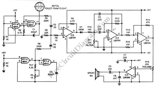
This schematic diagram illustrates a single-chip Theremin circuit. A Theremin is an electronic musical instrument that detects hand movements to control tones and frequency. The circuit employs two separate Colpitts LC oscillators to generate a beat frequency. The frequencies...
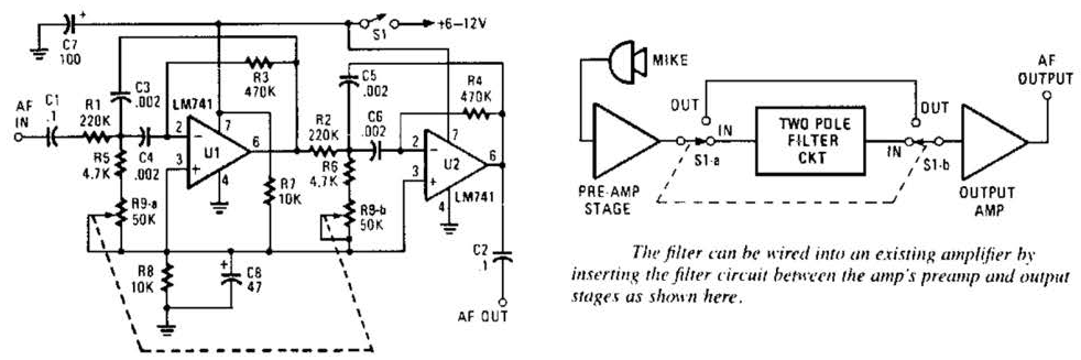
This variable-frequency audio bandpass filter is constructed using two 741 operational amplifiers connected in cascade. The two 741 op amps are configured as identical RC active filters and are cascaded to enhance selectivity. The filter's tuning range spans from...

This 1000-watt power inverter circuit diagram is based on the MOSFET RF50N06. For increased power output, additional MOSFETs can be paralleled with the RF50N06. These MOSFETs are rated for 60 volts and 50 amps. It is essential to connect...
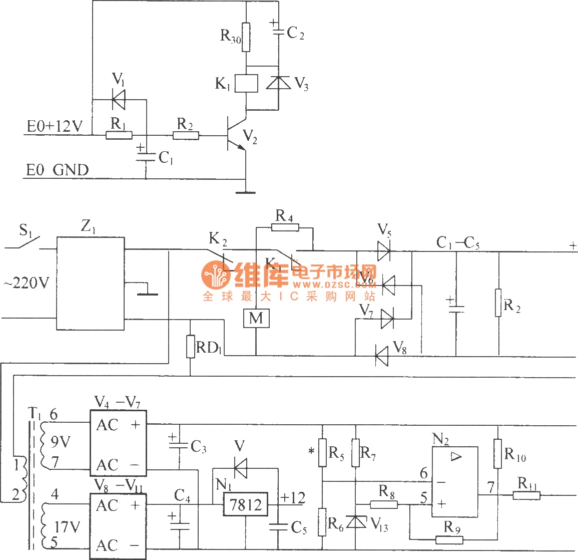
220V (5Hz) alternating voltage passes through the Z1 circuit filter, which filters the signal before sending it to the connection point of the AC over-voltage and under-voltage protection relay K2. During normal operation, the K2 connection point should be...
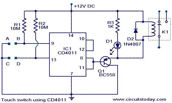
The following circuit illustrates a Touch Switch Circuit Diagram. This circuit is based on the CD4011 IC. Features include R1 and R2, which are the logic gates of the circuit. The Touch Switch Circuit utilizes the CD4011 integrated circuit, which...
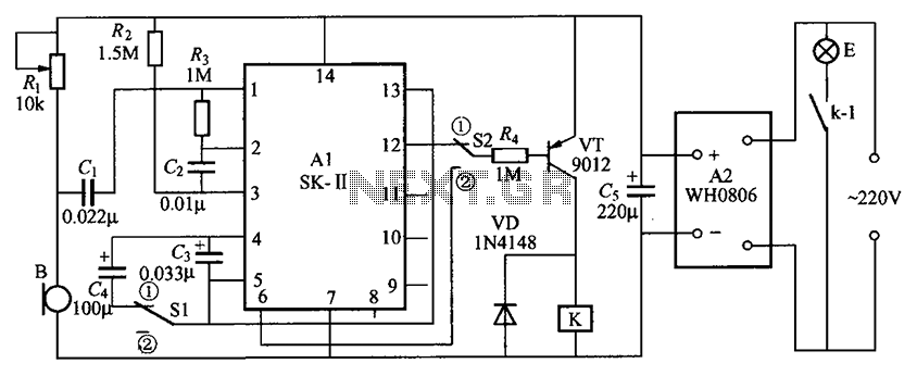
The circuit consists of an acoustic sensor, SK voice circuit, relay control circuit, vocal music circuit, and an AC buck rectifier circuit. The described circuit integrates several key components, each serving a distinct function to achieve the desired operational characteristics....