
Signal-injector

This unit is a single oscillator built around an LF351 JFET-input operational amplifier. Resistors R1 and R2 bias the non-inverting input, while resistor R3 biases the inverting input from the output. This configuration provides 100% negative feedback; however, the decoupling effect caused by capacitor C2 results in reduced feedback and high voltage gain when processing audio frequencies. The fundamental operating frequency is approximately 800 Hz. Potentiometer R4 serves as the output level control. To use it, start at the speaker. If no tone is heard, trace back to the amplifier input and listen for the tone. If still no tone is detected, continue backtracking from the output to the input, examining all stages in between. The stage where the signal is lost indicates the component that is not functioning.
The oscillator circuit utilizes the LF351 operational amplifier, which is known for its low noise and high input impedance characteristics, making it suitable for audio applications. The configuration of resistors R1 and R2 establishes a biasing network for the non-inverting input, ensuring that the operational amplifier remains in the active region for oscillation. Resistor R3 connects the output back to the inverting input, creating the necessary feedback loop that is essential for oscillation.
Capacitor C2 plays a critical role in controlling the feedback characteristics of the circuit. By introducing a decoupling effect, it allows for a reduction in feedback at higher frequencies while enhancing voltage gain, which is particularly beneficial for audio signals. The fundamental frequency of oscillation, set at approximately 800 Hz, is determined by the values of the resistors and capacitors in the circuit, which can be adjusted to achieve the desired output frequency.
Potentiometer R4 provides a means to adjust the output level of the oscillator, allowing for fine-tuning of the signal strength before it is sent to the speaker. This flexibility is essential in audio applications where varying output levels may be required.
In troubleshooting the circuit, if no tone is initially detected at the speaker, it is advisable to systematically trace the signal path back to the amplifier input. This involves checking each stage of the circuit for proper operation. The absence of a tone at any stage indicates a potential fault in that particular component or connection, which must be addressed to restore functionality to the oscillator circuit.This unit is a single oscillator built around an LF351 JFET-input op amp. Resistors Rl and R2 bias the noninverting input while R3 biases the inverting input from the output. This layout provides lOO% negative feedback, but the decoupling caused by C2 gives reduced feedback and high-voltage gain when dealing with audio frequencies.
The fundamental operatiog frequency is about 800 Hz. Potentiometer R4 is the output-level control. Th use it start at the speaker. Ifno tone is heard, move back to the amplifer input, and listen for the tone. Still if no tone is heard, continue backtracking from the output to the input, covering all stages in between. The stage where the signal is lost is the one that is not operating.
Related Circuits
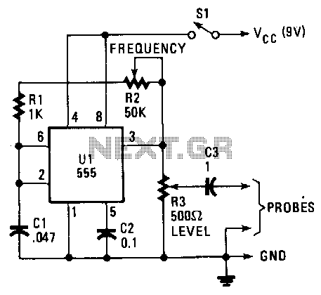
The unit provides a square-wave output that is rich in harmonic content. The circuit's output frequency can be varied from 50 Hz to 15 kHz. The heart of the circuit is a 555 astable connected in its equal mark/space...