
Signal-injector

The unit provides a square-wave output that is rich in harmonic content. The circuit's output frequency can be varied from 50 Hz to 15 kHz. The heart of the circuit is a 555 astable connected in its equal mark/space mode. The frequency is controlled by potentiometer R2 and capacitor C1. Resistor R3 controls the output level, with the output AC-coupled through C3.
The circuit operates based on the principles of a 555 timer configured in astable mode, generating a continuous square wave. The frequency of oscillation is determined by the values of R2 and C1, where R2 is a variable resistor (potentiometer) that allows for fine-tuning of the frequency output. The capacitor C1 works in conjunction with R2 to set the timing intervals, thus controlling the mark/space ratio of the square wave.
The output frequency range of 50 Hz to 15 kHz allows for versatility in various applications, from audio signal generation to clock pulses in digital circuits. The harmonic content of the output signal is a result of the sharp transitions between high and low states, characteristic of square waves, which can be advantageous in applications requiring rich signal content.
Resistor R3 is employed to adjust the amplitude of the output signal, providing a means to control the output level without affecting the frequency. This is particularly useful in interfacing with other circuit components that may require specific voltage levels. The output is AC-coupled through capacitor C3, which blocks any DC offset in the signal, ensuring that only the AC component is passed to the next stage of the circuit. This arrangement is essential for preventing unwanted DC levels from interfering with subsequent processing stages.
Overall, this circuit design is effective for generating square-wave signals with adjustable frequency and amplitude, making it suitable for a variety of electronic applications.The unit provides a square-wave output that is rich in harmonic content. The circuit"s output frequency can be varied from 50 Hz to 15 kHz. The heart of the circuit is a 555 astable connected in its equal mark/space mode. The frequency is controlled by potentiometer R2 and capacitor Cl. Resistor R3 controls the output level with the output ac-coupled through C3.
Related Circuits
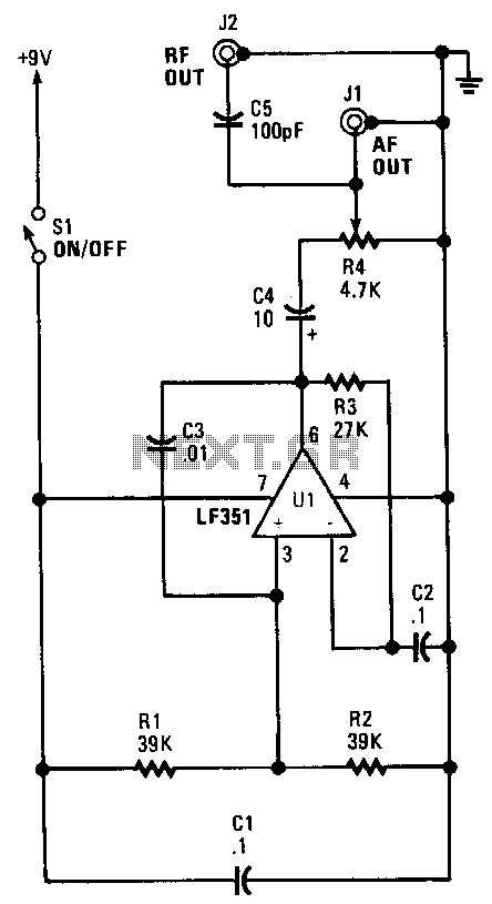
This unit is a single oscillator built around an LF351 JFET-input operational amplifier. Resistors R1 and R2 bias the non-inverting input, while resistor R3 biases the inverting input from the output. This configuration provides 100% negative feedback; however, the...