
simple 2 watt small switching power

This switching power supply circuit is designed to convert a DC input voltage into a regulated output voltage using a Schmitt trigger oscillator for efficient switching. The oscillator generates a square wave signal that drives a bipolar junction transistor (BJT) or a MOSFET. When the transistor is turned on, current flows through the inductor, causing it to store energy in the form of a magnetic field. The inductor is typically chosen for its high quality factor (Q), which minimizes energy losses during this process.
As the transistor turns off, the magnetic field collapses, and the stored energy is released into the load circuit. The release of energy raises the output voltage, which is then regulated by a zener diode positioned in the feedback loop. The zener diode clamps the output voltage to a predetermined level, in this case, around 14 volts. This feedback mechanism ensures that the oscillator stops operating when the output voltage reaches the zener's breakdown voltage, preventing overvoltage conditions.
The output voltage can be fine-tuned by adjusting the resistor values in the voltage divider network that feeds the zener diode. This flexibility allows for the output voltage to be tailored to specific application requirements. The load resistance influences the output voltage as well; higher load resistance will result in a higher output voltage, while lower resistance will decrease it.
The overall efficiency of the power supply is approximately 80%, which is a significant factor for applications requiring energy conservation. The use of a high Q inductor is crucial in achieving this efficiency, as it reduces resistive losses during the energy transfer process. This design is suitable for compact electronic devices where size and efficiency are paramount, making it an ideal choice for various applications in consumer electronics, automotive systems, and portable devices.In this small switching power supply, a Schmitt trigger oscillator is used to drive a switching transistor that supplies current to a small inductor. Energy is stored in the inductor while the transistor is on, and released into the load circuit when the transistor switches off.
The output voltage is dependent on the load resistance and is limited by a zener diode that stops the oscillator when the voltage reaches about 14 volts. Higher or lower voltages can be obtained by adjusting the voltage divider that feeds the zener diode. The efficiency is about 80% using a high Q inductor. 🔗 External reference
Related Circuits

Some amplifier is based around a RF transistor. In my case I will use a common NPN RF transistor called 2SC1970. You can also use other transistors like 2N4427 and some others. Check datasheets to see how much power...
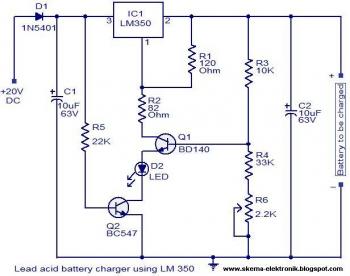
The circuit is designed as a constant voltage source with a negative temperature coefficient. The transistor Q1 (BD 140) serves as the temperature sensor, while transistor Q2 prevents battery discharge through resistor R1 when mains power is unavailable. The...
The system utilizes a single circuit breaker instead of fuses. According to the schematic, switches provide 12 volts of power and ground to the window motors in opposite polarities, allowing the windows to move up and down. Troubleshooting should...
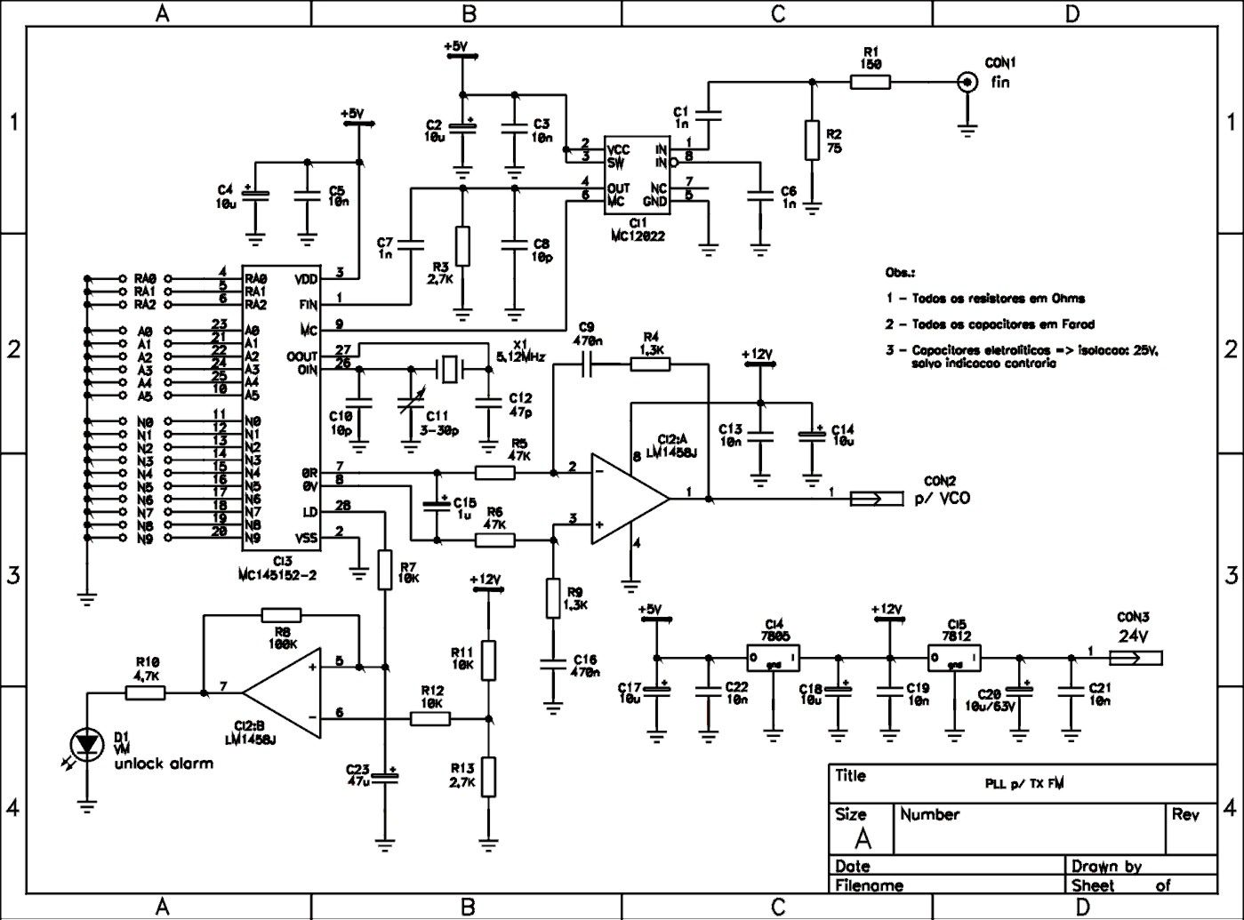
This is a schematic of a synthesized Phase-Locked Loop (PLL) for a low-power FM transmitter. It can also be utilized with other circuits, provided that the loop filter response, components, VCO tank circuit, and appropriate thumbswitch programming keys and...

In the example above, a low voltage (12V DC) is utilized to activate a relay that switches a 240V AC main circuit. It is important to note that there is no electrical connection between the two circuits within the...
This application note outlines the design of a PC-based, 14-bit data acquisition system. It adopts a systematic approach, incorporating all essential components: analog, digital, hardware, and software. The document elaborates on each phase, emphasizing the testing of individual systems...