
relay found in switch mode power supply

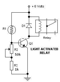
The described circuit utilizes a low-voltage control mechanism to operate a high-voltage load safely. The relay serves as an isolating switch, ensuring that the low-voltage control circuit does not come into direct contact with the high-voltage AC circuit, thus providing safety and preventing potential hazards.
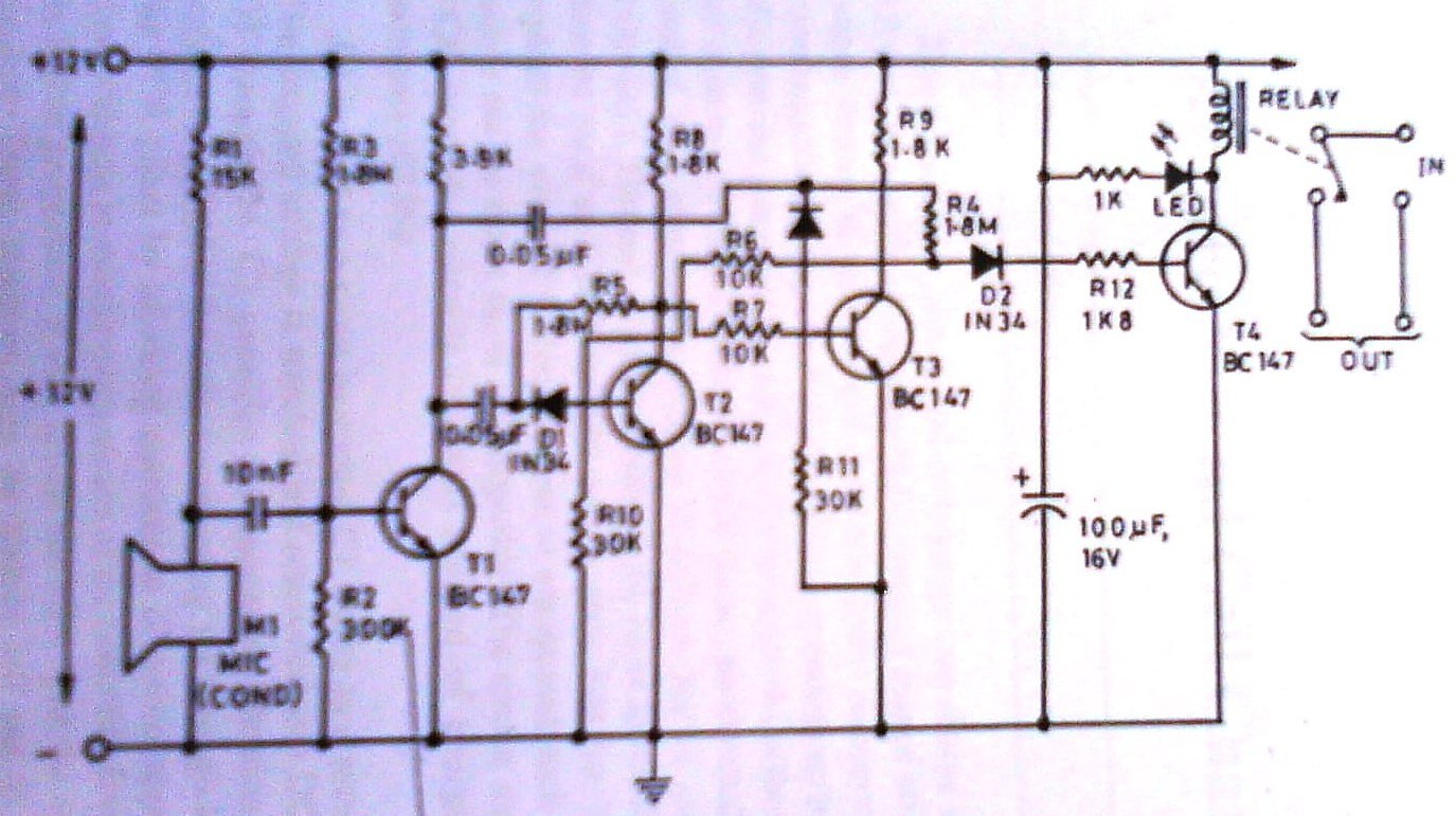
In this configuration, the transistor Q1 acts as a switch that controls the relay coil. When the base of Q1 receives a sufficient voltage, it allows current to flow from the 12V rail through the relay coil, energizing it. This energization creates a magnetic field that moves the relay's armature, closing the contacts and allowing current to flow through the 240V AC circuit.
The role of the microprocessor in the television is crucial, as it initiates the relay operation by sending a brief activation signal to Q973, which in turn controls the relay coil. This sequence ensures that the degaussing coil is activated only during the initial power-up phase, helping to eliminate any unwanted magnetic distortions on the screen.
Testing procedures for both the relay coil and contacts are essential for maintenance. The diode test on the coil checks for continuity, confirming that the coil has not burned out. The contact test ensures that the relay can effectively switch the AC load on and off, which is critical for the reliable operation of the entire circuit. This combination of components and testing methods provides a robust solution for controlling high-voltage devices using low-voltage control signals.In the example above a low voltage (12Vdc) is used to turn on a relay to switch on a 240V ac main circuit. Please note that there is no electrical connection inside the relay between the two circuits, the link is only magnetic and mechanical.
If there is Zero (0) volt at the Base (B) of transistor Q1. The transistor is open and therefore current is not able to flow from the 12V rail to the Ground and hence the relay contacts are open and the 240V ac Bulb is off. Now if a Voltage is applied at the Base (B) of transistor Q1. The transistor will close(ON) and the current will start flowing from the 12V rail through the relay coil to the Collector of the Q1 down to the Ground. When the current flow through the coil a magnetic field is created around the wire and this magnet (electro) will attract the contacts of the relay.
Once the contacts closes then the other circuit is switched on and the Bulb light. When the Television is first switched on a signal is send from the TV micro processor to the base of Q973 just for a moment (2 seconds). When this signal reaches the base of transistor Q973 the transistor is turned ON and the 12 Volts DC moves to the ground via relay coil.
When current flow through the relay coil it behaves like a magnet and relay switch (contacts) is closed. When the relay switch is closed the current flow through the relay on the 240V ac into the Degaussing Coil and the screen is cleaned.
Coil: Use your meter set to diode test and you should get a reading if the coil is okay. If no reading then the coil is open and therefore the relay is bad. Contacts: To test if the contacts are working you need to apply some Voltage (5V dc) to the two pins of the coil and if the contact is working then you should hear a click sound from the relay. 🔗 External reference
Related Circuits
This light-dark switch activated relay circuit schematic represents one of the simplest electronic circuits designed to activate other electronic devices based on light or darkness. It requires a single electronic relay and a few common components that are not...
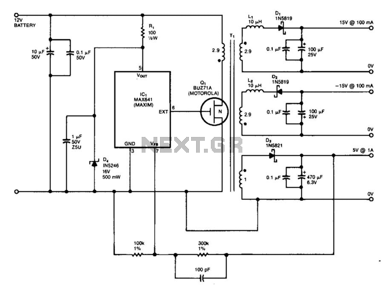
IC1 is a switching regulator that generates a 45-kHz signal to drive the gate of MOSFET Q1. Diodes D1, D2, and D3 are Schottky diodes. The 5-V output is monitored as a reference; feedback to the chip disables the...
This article aims to utilize an old PC as a simple controller. Many outdated PCs, such as the 8088, 8086, 80286, 80386, or even 80486, have become obsolete systems. This design employs an 8-bit LPT printer parallel data port...
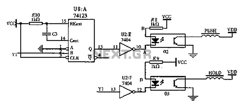
The FIG switching solenoid driver circuit utilizes the 74123 device chip (U8) and solid-state relays (02, 03). The switching electromagnet coil is referred to as the PUSH coil, while the HOL is maintained at a power supply voltage (VDD)...
This clap switch can turn on and off a light, fan, music system, or alarm—virtually any gadget—at the sound of a clap. The most remarkable feature of this design is its ability to provide efficient two-state control without the...
After one has built a QRP transmitter, it would be interesting to know the exact amount of output power. Without a power meter, the peak to peak voltage Vss is measured at a 50-ohm resistance (dummy load) with the...