
simple 20 watt tube emergency light

The home emergency light circuit is designed to provide illumination during power outages using minimal components, making it cost-effective and accessible for hobbyists and DIY enthusiasts. The circuit typically consists of a transformer, a transistor, a tube light, and a few passive components such as resistors and capacitors.
The transformer plays a crucial role in stepping up the voltage. In this design, the 12-0-12 volt transformer is configured to provide the necessary voltage to the tube light when the circuit is activated. The primary winding receives power, and the oscillations created in the primary induce a higher voltage in the secondary winding. This induced voltage is what powers the tube light.
The choice of the transistor is also important for the circuit's operation. The 2N6101 transistor is selected for its ability to handle the required current and voltage levels. Alternative transistors like the 2N3055 or D1351 can be substituted, although they may affect performance characteristics such as switching speed and current handling. It is essential to ensure that the transistor can handle the load presented by the tube light.
In terms of circuit performance, while the design is capable of producing light, it may not achieve the full brightness specified for the tube light. This limitation is attributed to the inherent characteristics of the circuit, including the efficiency of the transformer and the properties of the chosen transistor. Therefore, while the circuit is functional and serves its purpose as an emergency light, users should have realistic expectations regarding its brightness output.
Overall, this circuit represents a straightforward approach to creating a home emergency lighting solution, utilizing readily available components and demonstrating essential principles of electronics such as voltage transformation and transistor switching.This simple home emergency lights uses very few components yet is able to produce a reasonable amount of light. The components used are very common and can be easily procured from the local electronic retailer. This oscillations forces an AC in the secondary winding of the transformer which is further induced into the primary of thetransformer
and stepped up to the corresponding rated value ofthe transformer. The transformer used is an ordinary 12-0-12 volt 1Amp rated, it can be retrieved from any old, junk power supply unit that might be lying in your electronic junk box. The transistor also is an ordinary type, here a 2N6101 is shown, but any other similar type will do. You may try a 2N3055 transistor or even a D1351 in place of the specified one. However you cannot expect full striking brightness from this circuit. When I tested this circuit, I could never bring the tube light to its actual specified striking brightness.
🔗 External reference
Related Circuits
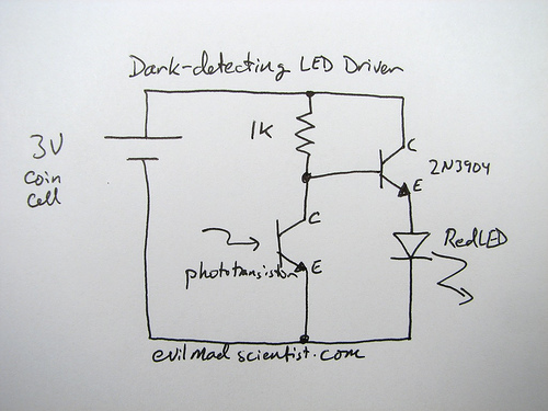
A circuit that uses a phototransistor to create a light-sensitive switch. When there is no light in the room, the LED connected to the phototransistor lights up, and when there is light, the LED turns off. Any schematic or...
This simple circuit is started running by connecting a twelve volt battery across the terminals, causing the large diameter Light-Emitting Diode to light up. When the battery is removed, the LED stays lit up because the circuit has become...
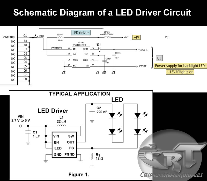
An LED (light-emitting diode) is utilized to illuminate keypad keys and LCD screen displays on all mobile phone handsets. It is controlled by the voltage or current drawn at its terminals. In the schematic diagram, the LEDs are driven...
The supply voltage should be about +/- 35 Volts at full load, which will let this little guy provide a maximum of 56 Watts (rated minimum output at 25 degrees C). To enable maximum power, it is important to...
It is assumed that most readers are considerate drivers who do not activate their rear fog lights when closely followed by other vehicles. Following drivers may mistakenly think that the vehicle is braking, leading them to react by applying...
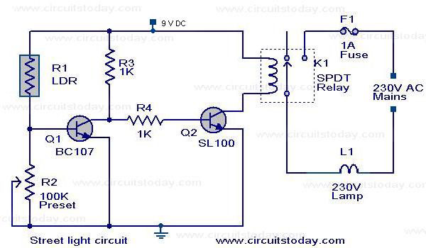
A street light that automatically switches ON when night falls and turns OFF when the sun rises. The circuit uses an LDR to sense the light. The automatic street light circuit functions by utilizing a Light Dependent Resistor (LDR) as...