
DEFROST TIMER CIRCUITS SCHEMATIC DIAGRAM

The timer circuit is designed to manage the operation of the compressor and defrost heater effectively. The single-phase synchronous motor provides reliable timing, ensuring the defrost cycle occurs at appropriate intervals. The use of a single-pole double-throw switch allows for seamless switching between the compressor and defrost heater, although care must be taken to avoid mechanical issues that could lead to simultaneous operation.
The schematic representation is critical for understanding the connections and operation of the timer. Each terminal's function is clearly defined, with terminal 1 serving as the common point for the switch, facilitating the transition between defrost and compressor modes. The continuous run timer variant demonstrates a more direct connection to the power source, allowing for uninterrupted operation of the timer motor, which is vital for maintaining the proper timing of the defrost cycles.
The operation of the timer is crucial in preventing ice buildup on the evaporator, which can impair system efficiency. By accurately controlling the defrost heater's operation, the timer ensures that the evaporator remains functional and that the compressor can operate effectively when needed. The design considerations, including the impedance of the timer motor, play a significant role in maintaining the integrity of the circuit and ensuring reliable performance. Overall, this timer circuit is an essential component in refrigeration systems, balancing the need for effective defrosting with the operational requirements of the compressor.The job of this timer is to disconnect thecompressor circuit and connect a resistive heatingelement located near the evaporator atregular time intervals. The defrost heater is thermostaticallycontrolled and is used to melt any frostformation on the evaporator.
The defrost heater ispermitted to operate for some length of time beforethe timer disconnects it from the circuit and permitsthe compressor to operate again. The defrost timer is operated by a single-phase synchronousmotor like those used to operate electricwall clocks, Figure 28 1. The contacts are operatedby a cam that is gear driven by the clock motor. A schematic drawing of the timer is shown inFigure 28 2. Notice that terminal 1 is connected tothe common of a single-pole double-throw switch. Terminals 2 and 4 are connected to stationary contactsof the switch. In the normal operating mode, the switch makes connection between contacts1 and 4. When the defrost cycle is activated, thecontact will change position and make connectionbetween terminals 1 and 2.
Terminal 3 is connectedto one lead of the motor. The other motor lead isbrought outside the case. It should be noted that the schematic drawingcan be a little misleading. In the schematicshown, the timer contact can only make connectionbetween terminals 1 and 4, or terminals 1 and 2. Inactual practice, a common problem with this timeris that the movable contact becomes stuck betweenterminals 4 and 2.
This causes the compressor anddefrost heater to operate at the same time. The schematic for the continuous run timer isshown in Figure 28 3. Notice in this circuit that thepigtail lead of the motor has been connected to terminal1, and that terminal 1 is connected directly tothe power source. Terminal 3 is connected directlyto the neutral. This places the timer motor directlyacross the power source, which permits the motor tooperate on a continuous basis.
Figure 28 4 shows the operation of the timer inthe compressor run cycle. Notice there is a currentpath through the timer motor and a path throughthe timer contact to the thermostat. This permitspower to be applied to the compressor and evaporatormotor when the thermostat closes. Figure 28 5 shows the operation of the circuitwhen the timer changes the contact and activates thedefrost cycle.
Notice there is still a complete circuitthrough the timer motor. When the timer contactchanges position, the circuit to the thermostat is openand the circuit to the defrost heater is closed. Theheater can now melt any frost accumulation on theevaporator. At the end of the defrost cycle, the timercontact returns to its normal position and permits thecompressor to be operated by the thermostat.
The cumulative compressor run timer circuit gets itsname from the fact that the timer motor is permittedto operate only when the compressor is in operationand the thermostat is closed. The schematic for thiscircuit is shown in Figure 28 6. Notice that thepigtail lead of the clock motor has been connected toterminal 2 instead of terminal 1.
Figure 28 7 showsthe current path during compressor operation. Thetimer contact is making connection between terminals1 and 4. This permits power to be appliedto the thermostat. When the thermostat contactcloses, current is permitted to fl ow through thecompressor motor, the evaporator fan motor, andthe defrost timer motor. In this circuit, the timermotor is connected in series with the defrost heater. The operation of the timer motor is not affected, however, because the impedance of the timer motoris much greater than the resistance of the heater.
For this reason almost all the voltage of this circuitis dropped across the timer motor. The impedance ofthe timer motor also limits the current fl ow 🔗 External reference
Related Circuits
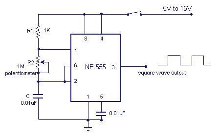
A NE555 integrated circuit (IC) is utilized for the design of a variable low-frequency oscillator, and a schematic is provided. The NE555 timer IC is a versatile and widely used device in various electronic applications, particularly in generating precise timing...
The overhaul includes features such as online judge diodes, the ability to test whether transistors are functioning properly, and the capability to assess TTL logic levels or high impedance states. It can output signals at 37 MHz, bar television...
The CX9800 models of mobile phones and desktop PCs feature a high-performance voice processing circuit that compresses the amplitude and bandwidth of the microphone signal. This design enhances the sensitivity of the microphone and its adaptability to varying distances....
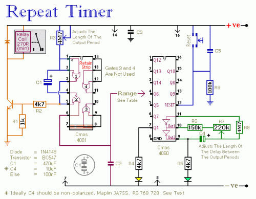
The following circuit illustrates a repeating interval timer circuit diagram utilizing the CMOS 4060 integrated circuit (IC). Features include its foundation on the CMOS 4060 IC and a 14-bit binary counter. The CMOS 4060 IC is a versatile component widely...

The circuit is designed to connect in parallel with a telephone, displaying the dialed number using DTMF (Dual Tone Multi-Frequency) signaling. It can also show the number dialed from the receiving party's phone, making it useful for capturing numbers...
Half of a Motorola MG14538B dual precision retriggerable monostable multivibrator is utilized to create an extended on-time timer circuit. This type of circuit can function as a switch debouncer. Such circuits are commonly implemented in digital applications, where every...