
Simple 6-Input Alarm

The alarm circuit is based on a single integrated circuit (IC), which serves as the core of the system, providing the necessary functionality for detection and alerting. The design is optimized for simplicity and ease of assembly, making it suitable for hobbyists and those with basic electronics skills.
The circuit typically includes a few essential components alongside the IC, such as resistors, capacitors, and a piezo buzzer for sound output. The resistors are used to set the sensitivity of the alarm and to limit current where necessary. Capacitors may be employed for noise filtering and stabilization of the power supply to the IC.
A motion sensor, such as a passive infrared (PIR) sensor, can be integrated into the circuit to detect movement within the garage or rumpus room. When motion is detected, the sensor sends a signal to the IC, triggering the alarm. The output from the IC can drive the piezo buzzer, producing a loud sound to alert occupants of any unauthorized entry.
The circuit can be powered by a standard DC power supply, making it easy to integrate into existing electrical systems. Additionally, the use of Veroboard allows for a compact and organized layout, facilitating troubleshooting and modifications if needed.
Overall, this alarm circuit is an effective solution for enhancing security in a multi-use space, providing a reliable alerting mechanism with minimal complexity in design and assembly.This simple alarm circuit was designed for use in a combined garage and rumpus room. It can be assembled on Veroboard and uses just one IC plus a handful.. 🔗 External reference
Related Circuits

Precious metals can sometimes be buried too deep to be detected without complex devices. However, smaller pieces of precious metals located near the surface can often be found using simpler methods. Many individuals are drawn to the prospect of...

A car alarm, in its simplest form, consists of one or more sensors connected to a siren. The most basic alarm features a switch on the driver's door, which is wired to trigger the siren when the door is...

This very simple circuit just uses a couple of resistors, a capacitor and the easily available 555 timer IC. The 555 is setup as an astable multivibrator operating at a frequency of about 1kHz that produces a shrill noise...

This circuit features a micro vibration sensor, a trigger delay circuit, and a control circuit, as illustrated in the accompanying figure. The micro vibration sensor comprises a vibration sensing device and a high power amplifier circuit, enabling it to...
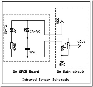
The following circuit illustrates a simple infrared sensor module circuit diagram. Features include a simple infrared sensor module and flame detection. The simple infrared sensor module circuit operates by utilizing an infrared (IR) transmitter and receiver pair. The IR transmitter...

The two circuits di atas illustrate opening a relay contact a short time after the ignition or light switch is turned off. The capacitor is charged and the relay is closed when the voltage at the diode anode rises...