
Simple Buzzer driver with 555

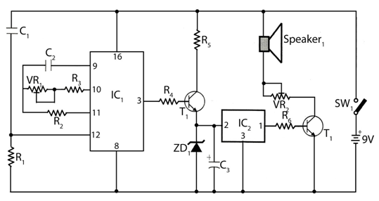
The circuit utilizes the popular 555 timer IC configured in an astable mode, which allows it to continuously oscillate between high and low output states without any external triggering. In this configuration, the 555 timer generates a square wave output, which can be used to drive a speaker or buzzer, producing an audible tone.
The timing components for the 555 timer in astable mode include two resistors (R1 and R2) and a capacitor (C1). In this case, one of the resistors is specified as 10KΩ, which can be adjusted to modify the frequency of oscillation. The second resistor's value can also be selected based on the desired frequency. The capacitor value will also influence the frequency; a typical choice might be in the range of microfarads (μF), depending on the desired output characteristics.
The frequency (f) of the output square wave can be calculated using the formula:
\[
f = \frac{1.44}{(R1 + 2R2) \cdot C1}
\]
Where R1 is the resistor connected from pin 7 (discharge) to Vcc, R2 is the resistor from pin 7 to pin 6 (threshold), and C1 is the capacitor from pin 6 to ground. The output frequency can be adjusted by changing the values of R1, R2, or C1, allowing for flexibility in sound generation.
When the circuit is powered, the 555 timer oscillates, causing the output pin (pin 3) to switch between high and low states, which drives the connected speaker or buzzer. The resulting sound is a shrill tone, which can be altered in pitch by varying the resistance and capacitance values. This simple circuit can be employed in various applications, such as alarms, sound effects in toys, or as a basic tone generator for educational purposes.This very simple circuit just uses a couple of resistors, a capacitor and the easily available 555 timer IC. The 555 is setup as an astable multivibrator operating at a frequency of about 1kHz that produces a shrill noise when switched on.
The frequency can be changed by varying the 10K resistor. 🔗 External reference
Related Circuits
Simple Burglar Alarm / Door Alarm Circuit Diagram. This project can be utilized to secure a door or window. It emits a loud beep and activates the room light when an intruder attempts to break the door lock. The Simple...

The circuit has been designed for telephone apparatus to indicate an incoming call as it rings using an LED for visual indication. BC550, an NPN general-purpose transistor, is utilized in the design. The circuit operates by detecting the ringing voltage...

This simple home alarm project can be used with a momentary contact from a motion detector to trigger an alarm similar to a police siren for a duration ranging from a few seconds to 220 seconds. The home alarm project...
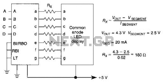
An IC1, such as the 7447, drives a common anode 7-segment LED display. The current-limiting resistor R must restrict the segment current to the rated value at the maximum supply voltage. A sample calculation is provided. The 7447 integrated circuit...
The circuit timer with a musical alarm utilizes a well-known CMOS oscillator/divider integrated circuit (IC1). Although this circuit operates at 9V, its standby current drain is minimal. The time delay of the timer circuit can be adjusted by modifying...
This temperature controller utilizes an LM135/235/335 temperature sensor and is designed to maintain a small environment at a warm or hot temperature. A schematic diagram is provided. The temperature controller circuit is centered around the LM135/235/335 series of temperature sensors,...