
Simple aircraft radio circuitWorking

The simple aircraft radio circuit typically consists of several key components that work together to facilitate communication between the aircraft and ground stations or other aircraft. The primary components include an antenna, a radio frequency (RF) amplifier, a mixer, a local oscillator, and a demodulator.
The antenna captures radio waves transmitted from ground stations or other aircraft. The RF amplifier boosts the weak signals received by the antenna to a level suitable for further processing. The mixer combines the amplified RF signal with a signal from the local oscillator to produce an intermediate frequency (IF) signal. This IF signal is easier to filter and demodulate than the original RF signal.
The demodulator extracts the audio information from the IF signal, allowing the pilot or crew to hear the transmitted voice communications. The output of the demodulator is typically fed into an audio amplifier, which drives a speaker or headset for clear audio output.
Power supply considerations are crucial in aircraft radio circuits. A stable and reliable power source is necessary to ensure consistent operation of all components. Additionally, proper shielding and grounding techniques are employed to minimize interference and enhance the overall performance of the radio system.
Overall, the design of a simple aircraft radio circuit emphasizes reliability, clarity of communication, and resistance to environmental factors such as vibration and temperature variations encountered during flight.The circuit diagram and detailed explanation of a simple aircraft radio circuit is given below.. 🔗 External reference
Related Circuits

The FM radio transmitter is a high-frequency amplifier circuit that utilizes the Mitsubishi frequency set, specifically the M57704H discharge path. It operates within the frequency range of 457-458 MHz and has a transmission power of 5 watts. As illustrated...

This article provides instructions for creating a light-sensitive morning alarm circuit. The circuit utilizes an LDR (Light Dependent Resistor) or photoresistor to detect morning light, which triggers the alarm section. When light is detected, the circuit produces a melodious...
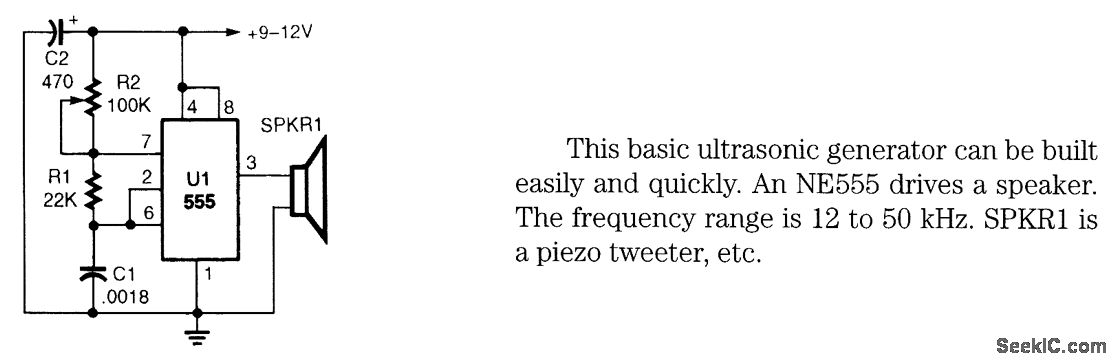
This basic ultrasonic generator can be built easily and quickly. An NE555 drives a speaker. The frequency range is 12 to 50 kHz. SPKRI is a piezo tweeter. The ultrasonic generator circuit utilizes the NE555 timer integrated circuit, which is...

This article discusses a simple five-channel radio remote control circuit utilizing the TX-2B and RX-2B integrated circuits from Silan Semiconductors. The TX-2B/RX-2B is a remote encoder-decoder pair suitable for remote control applications. It features five channels, a wide operating...

This is a simple audio microphone preamplifier circuit based on a single LM358 IC. The circuit is straightforward, cost-effective, and easy to construct. The component parts list includes: R1, R3, R4 = 10K; R2 = 1K; R5 = 100K-1M...

The servo motor has numerous applications in various fields, including robotics, puppetry, photography, and more. These compact motors can accurately position their output shaft to any specified angle and maintain that position. Most servos have a motion range of...