
simple mic pre-amp based LM358

The LM358-based audio microphone preamplifier circuit is designed to amplify low-level audio signals, making it suitable for use with electret microphones. The circuit's architecture employs a dual operational amplifier, allowing for a compact design while providing sufficient gain. The resistors and potentiometer values are selected to optimize the input impedance and gain characteristics, ensuring compatibility with various microphone types.
In the more complex 12AX7 microphone preamplifier circuit, the use of vacuum tubes introduces unique audio characteristics, often preferred for their warmth and harmonic distortion. This circuit requires careful construction and tuning, suitable for individuals with intermediate or advanced skills. The choice of capacitors, particularly those rated at 33uF, is critical for coupling and decoupling purposes, ensuring that the audio signal remains intact while blocking DC offsets.
The dynamic microphone compressor circuit enhances audio signals by managing dynamic range, which is crucial for achieving professional sound quality. The integration of multiple transistors allows for effective signal processing, with the first stage amplifying the microphone signal, the second stage buffering the output, and the third stage providing feedback for stability. This configuration is essential for maintaining consistent audio levels, particularly in live sound applications.
The 2N3904 transistor-based preamplifier circuit is an excellent choice for applications requiring low power consumption without sacrificing audio quality. Its straightforward design makes it accessible for beginners, while still providing adequate performance for various audio projects. The use of negative feedback through R6 ensures that the amplifier operates within its optimal range, minimizing distortion and enhancing fidelity.
Overall, these circuits exemplify fundamental principles in audio electronics, showcasing various methods for amplifying and processing audio signals. They are suitable for a range of applications, from simple DIY projects to more complex audio systems.Here the simple audio mic pre amplifier circuit based on single IC LM358. The circuit is very simple, inexpensive and easy to built. Component Parts List: R1, R3, R4 = 10K R2 = 1K R5 = 100K-1M Potensiometer C1 = 0. 1uF C2 = 4. 7uF/16V IC1 = LM358 dual op-amp single supply Mic = Electret Microphone. The following diagram is the circuit diagram of tu be mic pre amplifier 12AX7. This circuit is little hard to built. You must have an intermediate or advanced skills to build this circuit. All capacitors with value of 33uF are 16V, while the all others are 50V unless marked otherwise. Resistors marked with "#" are 1%. The circuit below is a Dynamic Mic Compressor circuit is simple but the results are quite satisfactory. Audio output sounded outstanding. The principle of this circuit is very simple, the first transistor is used as Mic Pre-Amp. Then a second transistor used as a buffer. And the third transistor is a feedback circuit. Supply voltage. This is a simple audio Pre-Amplifier with single transistor 2N3904. This easy circuit provides good gain to weak audio signals such as electret microphone. Use it in front of an RF oscillator to make an RF transmitter that`s very sensitive to sound. This circuit consume low current supply (about 2mA), so will have a long battery life for supplying the circuit.
The circuit built based on a low noise, high gain two stage PNP and NPN transistor amplifier, using DC negative feedback through R6 to stabilize the working conditions quite precisely. Below is a mic compressor circuit that uses transistors as active components. VR1 and VR 2 is used to control the tone from the microphone, while VR3 and VR4 strengthening works to control the audio signal in the compressor mic.
C10 must be used in this circuit. The circuit I got from my local computer. 🔗 External reference
Related Circuits

Do not let its extreme simplicity deceive you — this device is useful! Many have been made over the years, and some have even been given away as gifts. Yes, multimeter... A multimeter is an essential instrument in electronics, used...
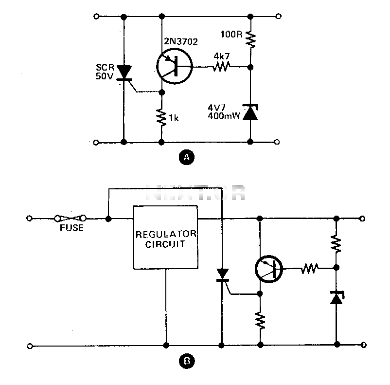
These circuits provide overvoltage protection in the event of a voltage regulator failure or the application of an external voltage. They are designed to be used with a power supply that includes some form of short circuit protection, such...
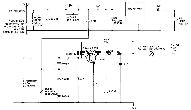
This circuit is designed for operation in the 80m band. It utilizes a 365-pF variable capacitor, specifically intended for the broadcast band, which should be equipped with a vernier drive featuring a six-to-one tuning ratio. This configuration enhances the...
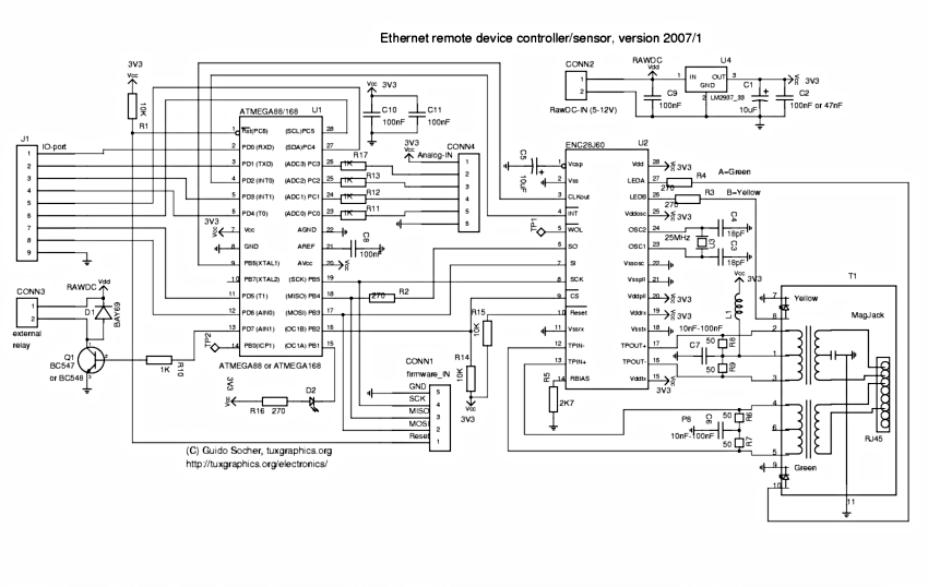
Ethernet has traditionally been a complex interface. All Ethernet chips up until now have had 100 pins or more, making them difficult to find in small quantities and challenging to use with microcontrollers that have limited memory. Microchip has...
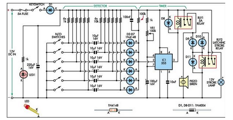
This simple alarm circuit was designed for use in a combined garage and rumpus room. It can be assembled on Veroboard and uses just one IC plus a handful of additional components. The alarm circuit is based on a single...
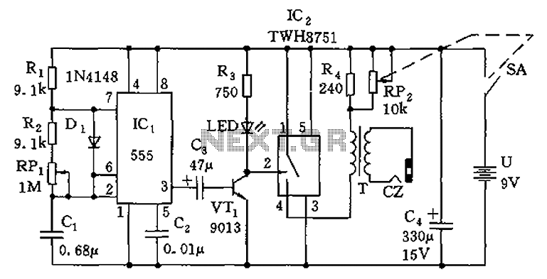
The circuit is composed of a 555 oscillator and an amplifier driver stage. It includes the 555 timer along with resistors R1, R2, RP1, capacitor C1, and other components forming a multi-harmonic oscillator. The frequency can be adjusted using...