
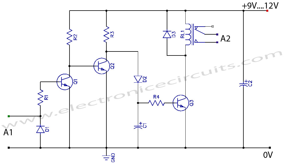
Simple condenser microphone mini audio amplifier circuit schematic

The circuit operates by first capturing sound waves through the condenser microphone, which generates a weak electrical signal. This signal is then fed into the base of transistor Q1, which is configured to amplify the signal. The 470kΩ resistor plays a critical role in stabilizing the operating point of Q1 by providing negative feedback, which enhances linearity and reduces distortion in the amplified output.
The output signal from the collector of Q1, which is significantly stronger than the input, is passed through a coupling capacitor (0.1 µF). This capacitor serves to block any DC component while allowing the AC audio signal to pass through to the base of transistor Q2. Transistor Q2 further amplifies the signal, providing an output that can drive subsequent stages of amplification or processing.
The choice of BC547 transistors is suitable for low-power applications, making this circuit ideal for battery-operated devices. The simplicity of the design, along with the minimal number of components required, facilitates easy assembly on a breadboard or PCB. This circuit can be an excellent choice for hobbyists and engineers looking for a cost-effective solution to amplify audio signals from microphones in various electronic projects.This is a very useful and simple circuit diagram for amplifying weak signal from a capacitive condenser microphone. You can use this circuit for sound sensing applications and some automatic robotic sensors. We have already posted an efficient audio amplifier circuit using 1895 IC, it is somewhat complicated and is suitable for very sensitive appl
ications. But this condenser microphone DIY audio sound amplifier is very small and simple to implement because it uses only two BC547 transistors and some discrete components. You can construct this circuit with a minimum price of $2. This circuit is apt for cheap amplification purposes in electronics such as pre amplifier for FM transmitters.
Transistor Q1 is configured as collector to base biasing mode. This is accomplished via 470k © resistance. This resistor provides negative feedback to the transistor Q1. The output of Q1 becomes available at the collector (across 3. 3k © resistor), which is the input to the transistor Q2 via a 0. 1 µF capacitor. The capacitor removes DC voltages due to the biasing of Q1. 🔗 External reference
Related Circuits
If a negative supply is required for an operational amplifier or if a negative bias voltage is needed while operating from a single supply voltage, such as in battery applications. To generate a negative supply voltage from a single positive...
The circuit operates at 380V for air flow. Power is supplied through a step-down transformer, which rectifies the output to 9V DC. When the pump operates correctly, a button labeled 'S' is activated. The circuit utilizes a TWH8778 component....
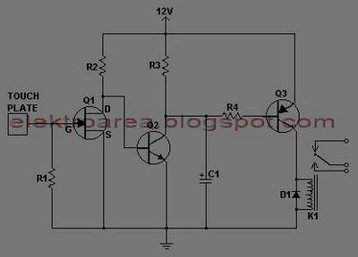
This document describes a series of touch switches that utilize only three transistors. These touch-based transistor switches can activate a load simply by the user touching a metal plate. They are designed to directly switch a relay, enabling operation...
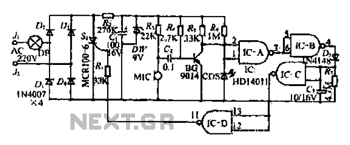
Prolonged reading or writing, maintaining a close distance between the eyes and the book, and insufficient lighting are primary contributors to decreased vision. This example describes a visual fatigue eliminator designed to alleviate eye fatigue and prevent myopia. The...
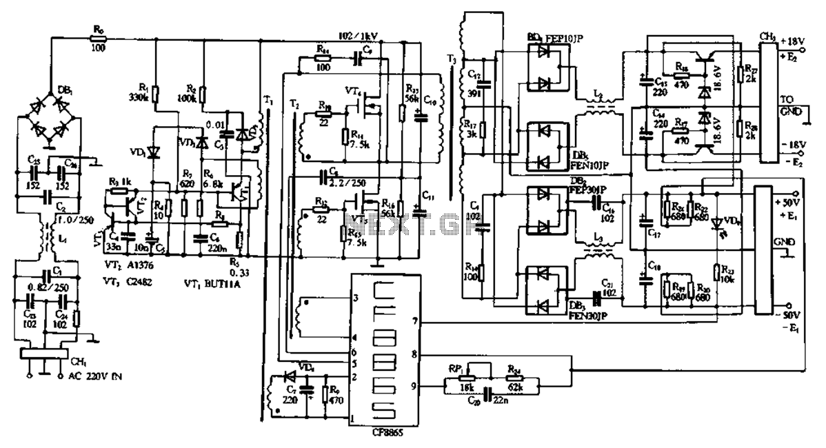
This document describes a specific module utilizing the CF8865 switching power supply circuit, which employs the integrated control module CF8865. In the figure, transistors VT4 and VTs are controlled by the excitation transformer Tz. The output is processed through...
VCR Camera Video Detector Switch Controller Circuit. This video detector switch controller circuit utilizes the video output from a VCR or camera to... This circuit functions as a video detector switch controller, designed to manage the video output from a...