
simple audio amplifier

The described circuit begins with a preamplifier stage that employs the 2N2222 transistor (Q1). This transistor serves as the input stage, amplifying weak signals before they are processed further. The configuration of Q1 allows for significant gain, which is crucial for improving the signal strength.
Transistor Q3 (2N3053) plays a critical role in this circuit as it is connected to the base of Q2 (2N2905A). This arrangement forms a complementary symmetry output stage, which is essential for driving the load effectively. The complementary pair configuration enhances the efficiency of the circuit by allowing for push-pull operation, where one transistor conducts during one half of the signal cycle while the other conducts during the opposite half. This results in improved linearity and reduced distortion in the output signal.
The output of the preamplifier can be obtained from the junction of the emitters of Q2 and Q3. This point serves as the amplified output, providing a stronger signal that can be fed into subsequent stages of the circuit, such as additional amplification or processing stages. The careful selection of transistors and their arrangement ensures optimal performance of the preamplifier, making it suitable for a variety of applications in audio and signal processing systems.The first part of the circuit here is a preamplifier consisting of transistor Q1(2N2222). The collector of the Q3 is coupled to the base of Q2 (2N2905A), which forms a complementary symmetry pair with Q3 (2N3053). The amplified signal is available at the junction of emitter of two transistors. 🔗 External reference
Related Circuits
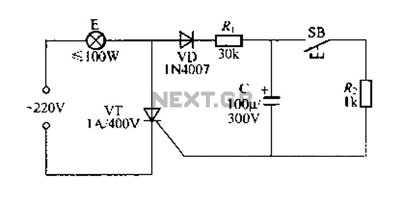
Figure 57 illustrates a simple delay lamp circuit that connects to lamp E using a two-wire connection. This design allows for the security bars to be installed directly, enabling replacement with a standard wall switch without altering the existing...
More: A comprehensive electronic schematic is required to illustrate the functionality and interconnections of various components within a circuit. The schematic should clearly depict the arrangement of components such as resistors, capacitors, diodes, transistors, and integrated circuits, along with...
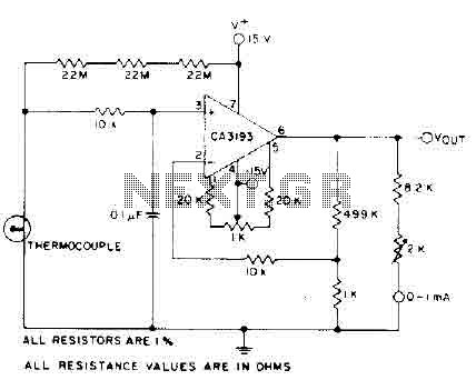
The circuit requires a 15-volt power supply and employs a precision operational amplifier, CA3193 BiMOS, to amplify the generated signal by more than 500 times. Three 22-megohm resistors are utilized to ensure a large-scale output in the event of...
The amplifier is capable of delivering around 1.5W into 8 ohm headphones, and 2.2W into 32 ohms - this is vastly more than will ever be needed in practice. The use of a 120 Ohm output resistor is recommended,...
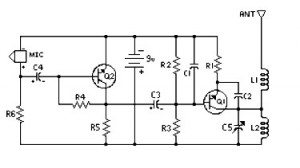
4 Stage FM Transmitter. This FM transmitter circuit utilizes four radio frequency stages, functioning as a VHF oscillator. It is available for wholesale through fmuser, including the CZE and CZH models of FM transmitters, which are suitable for OEM...
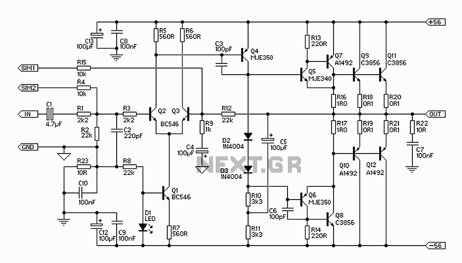
The 300W amplifier circuit presented is a conventional design. It includes connections for the internal SIM and incorporates filtering for RF protection (R1, C2). The input is facilitated through a 4.7µF bipolar capacitor, which offers substantial capacitance in a...