
Battery state of charge indicator circuit

The circuit involves two light-emitting diodes (LEDs) serving as indicators for the battery charging status. The green LED (VLi) is connected in parallel with the battery and is configured to light up when the battery voltage reaches a predetermined threshold, indicating that the battery is adequately charged. This is typically achieved through a voltage divider or a comparator circuit that senses the battery voltage and activates the green LED accordingly.
Conversely, the red LED (VLz) functions as a low battery indicator. It is also connected to the same battery circuit but is designed to illuminate when the battery voltage falls below a certain level. This can be implemented using a similar voltage sensing mechanism, where the circuit detects insufficient voltage and triggers the red LED to signal that the battery requires charging.
Both LEDs can be connected to a common ground, and appropriate current-limiting resistors should be included in series with each LED to prevent excessive current flow, which could damage the diodes. The use of these indicators enhances user experience by providing clear visual feedback regarding the battery status during operation and charging, ensuring that the user is informed about the battery's condition at all times.When charging, the green light-emitting diode VLi; the battery is sufficient, red light-emitting diode tube VLz bright.
Related Circuits
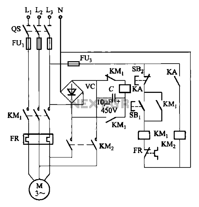
The circuit depicted in Figure 3-137 eliminates the need for a step-down transformer by utilizing the principle of energy storage capacitor discharge for braking. It can be employed to transform the power of motors with a rating of less...

To charge lead-acid batteries, a circuit can be utilized that consists of a current-limited power supply and a flyback converter topology. The described circuit for charging lead-acid batteries employs a current-limited power supply in conjunction with a flyback converter...
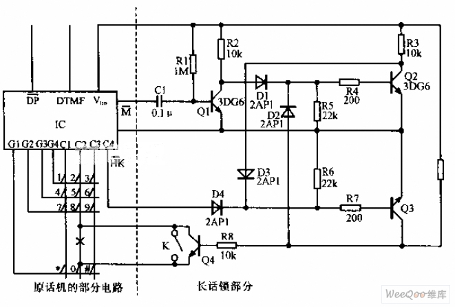
A simplified long-distance call lock is illustrated in the accompanying image. This device is designed to prevent long-distance calls while maintaining the original functionality of the phone. Although it consumes power, it exhibits excellent compatibility. When switch K is...

The ordinary triode 3DA87C is utilized to create a long-range FM transmitter circuit, which functions as a standard three-point oscillator circuit. This remote transmitter circuit is capable of large current emissions, achieving a range of up to 1 kilometer...
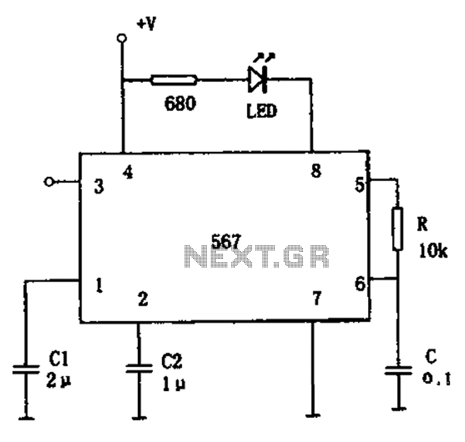
The FM demodulation circuit is illustrated in Figure 567. The FM signal is input at pin 3, and the demodulated signal is output from pin 5. The center frequency of the FM demodulation circuit is determined by the formula...

This alternator regulator utilizes a 3-transistor DC amplifier and is designed for a pulled-up field system, where one side of the alternator field returns to the +12V supply, and the other end is pulled toward ground. The circuit monitors...