
Simple bike computer tutorial

The PCB design serves as a critical platform for integrating various electronic components necessary for the bicycle's operation. The inclusion of a Hall effect sensor is essential for detecting the wheel's rotation, which is fundamental for speed measurement and distance calculation. The sensor's placement must ensure optimal interaction with a magnet attached to the wheel or another moving part of the bicycle.
Incorporating a Hall effect sensor into the circuit requires careful consideration of the power supply and signal conditioning. The sensor typically operates on a low voltage, often around 5V, and the output can be interfaced with a microcontroller or other processing unit. The output signal from the Hall sensor is a digital pulse that corresponds to the presence or absence of the magnetic field, allowing for accurate speed calculations.
To ensure proper functionality, the circuit should include a pull-up resistor connected to the output of the Hall sensor. This resistor helps to stabilize the signal and prevent floating states, which can lead to erroneous readings. The choice of resistor value is crucial; a common value is around 10k ohms, but this may vary based on the specific requirements of the application.
Testing the sensor's operation can be performed using a multimeter, as previously described. The resistance readings when a magnet is brought close to the sensor should show a significant drop, confirming the sensor's operational integrity. Additionally, it is advisable to verify the sensor's response at various distances and angles relative to the magnet to ensure consistent performance.
Overall, the integration of a Hall effect sensor into the bicycle's electronic system enhances its functionality, providing real-time data essential for performance monitoring and user feedback. Proper circuit design and testing are paramount to achieving reliable and accurate measurements, ultimately contributing to the overall effectiveness of the bicycle's electronic features.The PCB we have made is big and has plenty of space for cutting and adding other bits and pieces. But if we want the final satisfaction of seeing it working, mounting the lot on a real bike, it is a bit too big. Way back in chapter one, we discussed sensors and I recommended we should stay with the herd and use some sort of hall device.
Well now w e physically need one to get our hands on. I realise that it is almost impossible to buy a potted sensor +cable as a spare, they all come with a bike computer. Now we could buy a complete bike computer kit and throw the computer away. Or keep it for later as a spare. So we have results similar to the diagram. Similar means there is a measurable resistance change when the magnet is passed over and CLOSE to, he sensor body.
How can we check I connected my multimeter on the mA scale across the end of the sensor wire in the handle bar mount shoe ( place where it enters the computer). The reading is of course zero mA. Next I took one of those little kitchen fridge magnets and waved it very close ( 1mm) to the Unknown type ” of sensor.
I had to find the best direction to move the magnet over the sensor, but eventually I got a reading of a about 50 uA Well I cheated as I knew it was a coil sensor, but if it hadn`t been a coil sensor, instead some sort of HALL device, then we would have no change at all when the magnet was passed across the sensor body. In that case we would need to condition the pulse output. For those interested, basically a limiting amplifier to ensure that even at the slowest speeds there is enough signal for the PIC to detect at the PORTB input.
But this could be tricky, without an oscilloscope, so unless you really have set your heart on making it work, best look for a HALL device type sensor. No panic about getting a voltage supply, lets look at the following drawing on how to test a HALL type sensor.
The voltmeter on the ohms range will normally give you the required voltage-. Once upon a time a man was playing about with, frogs legs, batteries etc, passing current through his solid iron (apparently Aluminium was too expensive in those days) breakfast tray. He simply clipped the battery across the ends and his DVM across the sides. He tried a lot of things to measure the voltage, but to no avail. However one day he was messing about with magnets trying to lift the iron tray when he noticed that the voltmeter which had been left by accident from the previous session, was reading a voltage!
He jumped up and shouted Eureka, ( was that someone else ), I will call this the quantum charge displacement effect. However the cleaning lady was becoming frustrated as all this was stopping her getting on with things The drawing shows what happens as we pass the magnet across a HALL sensor.
In my case I had one that gave a change of reading from megohms to kiloohms. A range of 1000 to 1. So let`s test yours. Don`t forget to select the OHMS function on your meter. The range is adjusted for best results. This depends on the device you have found/bought. Caution. The battery here is inside the DVM, and is current limited. The hall device doesn`t care really which way you apply the battery vpltage but the amplifiers and circuits for conditioning do. Other sensors will read with the DVM ( as battery) both ways ( depends on the internal circuitry). Here the correct battery polarity is when there the reading with magnet is much larger than the reading without.
Using the ohms reading:- away from the magnet is HIGH ohms, magnet present is LOW ohms, the reverse of the volts readings. Looking at the snippet of our theoretical circuit we have a large resistor, 100k between the 5V battery and the sensor.
Even if the sensor becomes a dead short wrong way round, the maximum current is 50uA, so this class of device is protected from. damage. Also note that the battery in the Bike computer box is also protected from external short circ 🔗 External reference
Related Circuits
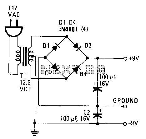
This power supply provides both +9 V and -9 V outputs to replace two 9-V batteries. The rectifier circuit consists of two separate full-wave rectifiers, each connected to the secondary winding of the transformer. The first full-wave rectifier, made...
The DC motor drive controller can control two DC motors of varying current or voltage ratings, depending on the relay specifications. The circuit includes two shaft encoders that provide positional feedback to a computer. The motor control circuit connects...
This article provides insights on how to interface infrared (IR) remote controllers with a computer. Possible applications include controlling a computer using a TV remote or managing a VCR through a computer. The circuit discussed was initially shared in...
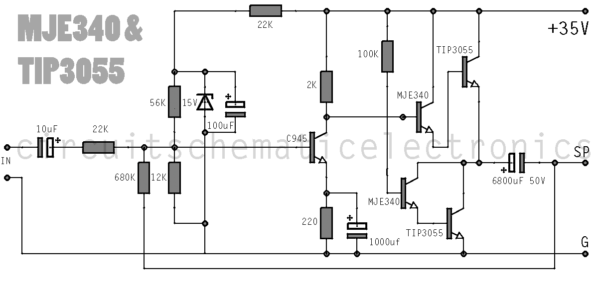
This simple amplifier delivers good sound quality with a power output of approximately 10 to 14 Watts and operates on a supply voltage of about 34 to 36 Volts DC. It requires a preamplifier due to its limited advanced...
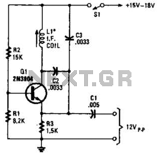
A simple oscillator for intermediate frequency (IF) alignment at 455 kHz can be useful in field testing or in scenarios where a standard signal generator is available. The inductor (L1) should resonate at the desired output frequency with the...
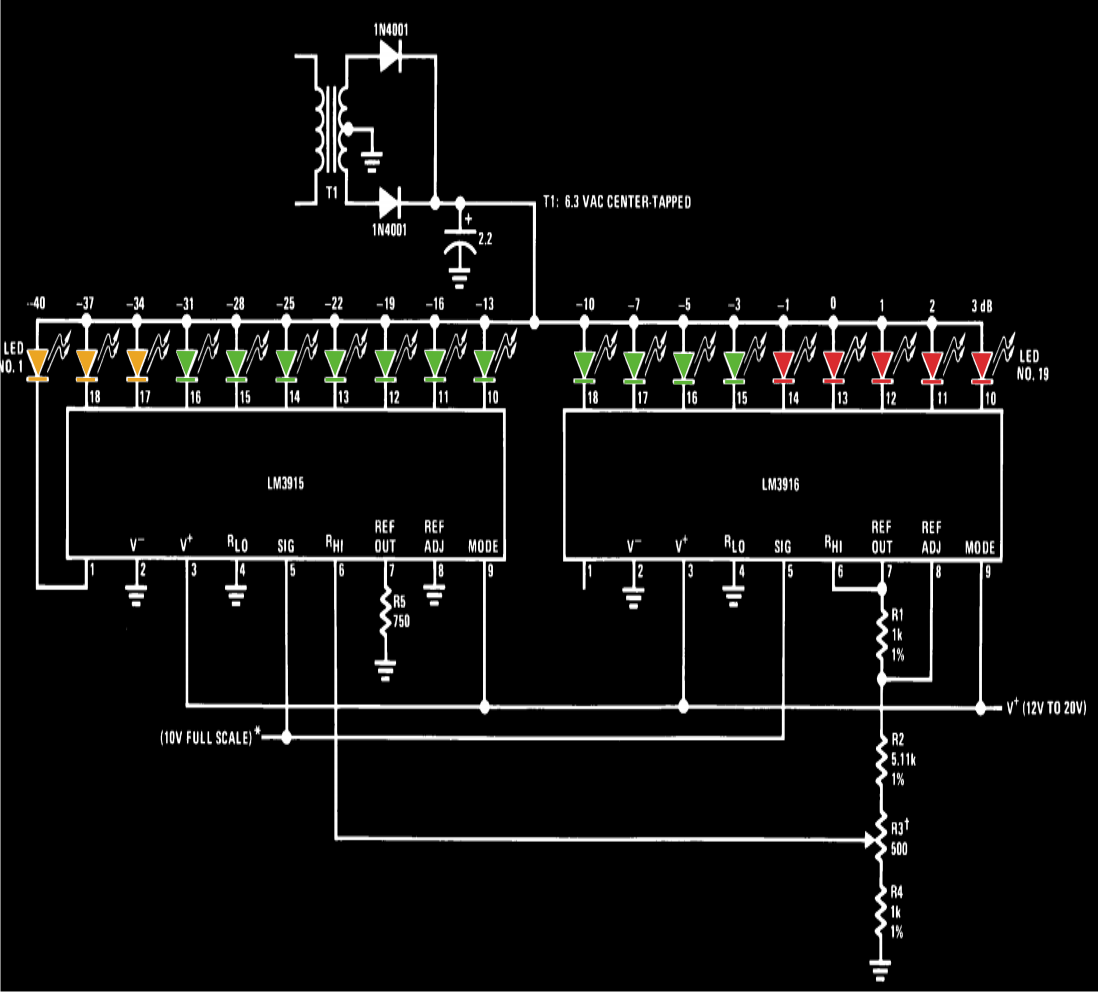
A VU meter, or volume unit meter, is a device used to indicate the music volume output from an amplifier or loudspeaker system. It can also be viewed as a device for displaying the PMPO (Peak Music Power Output)...