
Simple Rf Test Oscillator Circuit

The oscillator circuit is designed to generate a stable sine wave signal at 455 kHz, commonly used in radio frequency applications, particularly for IF alignment in superheterodyne receivers. The circuit typically consists of an inductor (L1) and two capacitors (C2 and C3) configured in a tank circuit that determines the resonant frequency.
The resonant frequency (f) of the LC circuit can be calculated using the formula:
f = 1 / (2π√(L * C))
where L is the inductance in henries and C is the total capacitance in farads. In this case, the total capacitance (C) is the series combination of C2 and C3, which can be calculated as:
1/C = 1/C2 + 1/C3
This configuration allows for fine-tuning the output frequency by adjusting the values of the capacitors. The oscillator can be powered by a low-voltage DC source, and it may include additional components such as resistors for biasing or feedback to stabilize the oscillation.
The output can be taken directly across the inductor or through a buffer stage to prevent loading effects that could alter the frequency. This oscillator can be employed in various applications, including signal generation for testing receivers, frequency calibration, and alignment procedures, making it a valuable tool for engineers and technicians in the field of electronics. A simple oscillator for IF alignment (455 kHz) can prove useful in field testing or where a standard signal generator is available. LI should resonate at the desired output frequency with the series combination of C2 and C3.
Related Circuits
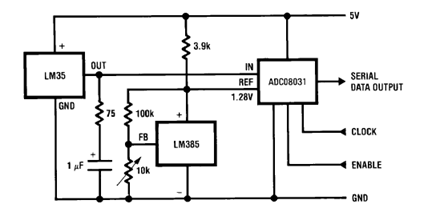
The circuit illustrates a Temperature to Digital Converter diagram utilizing the LM35 sensor, which includes a beneficial bypass capacitor connected from VIN to ground and a series RC damper. The described circuit employs the LM35 temperature sensor, a precision integrated...
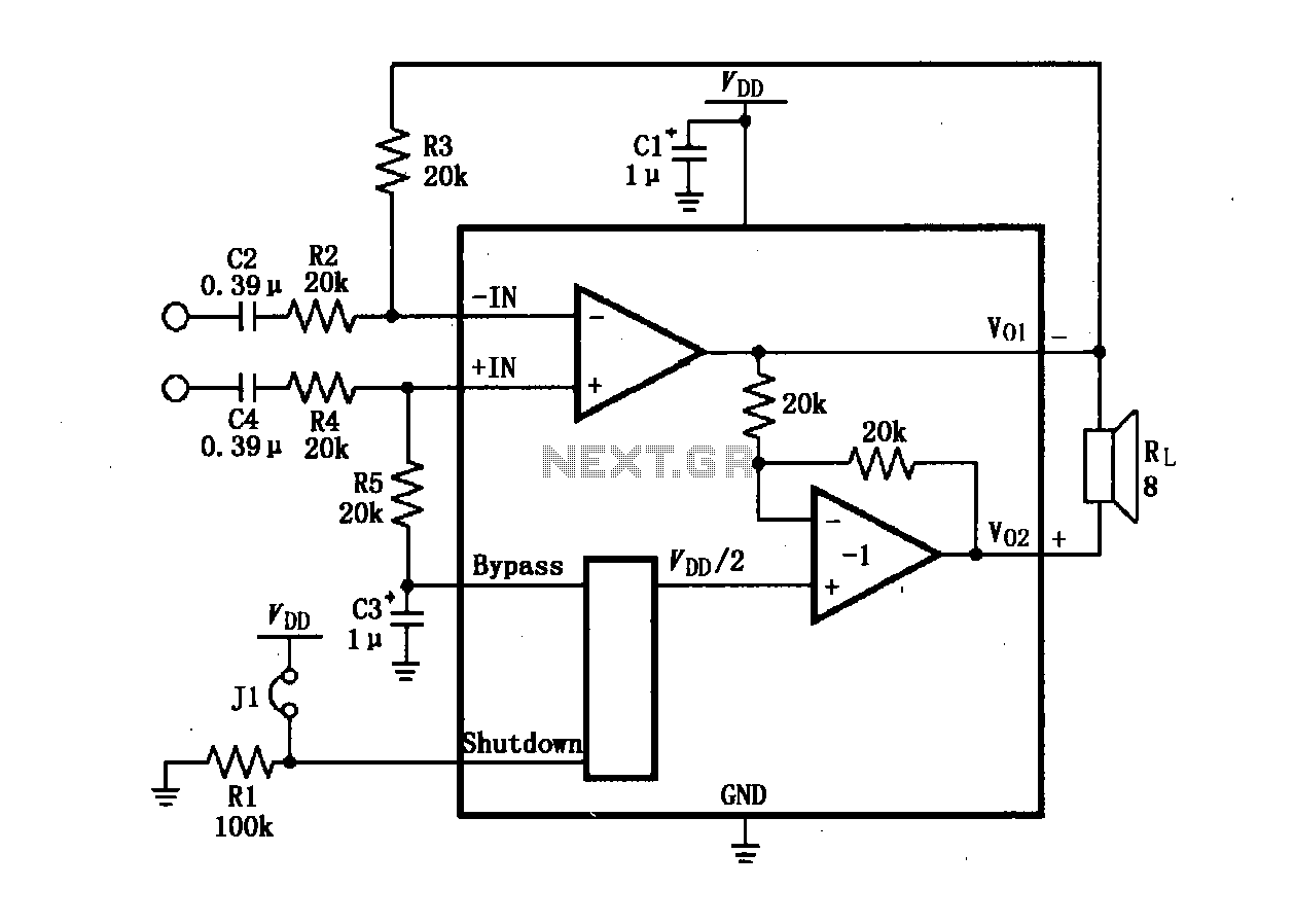
The LM4904 audio input differential amplifier circuit is presented. The audio signal is provided as a differential input to the +IN and -IN terminals. The LM4904 is a low-power audio input differential amplifier designed for high-performance audio applications. This circuit...
This circuit switches a printer's USB connection from a PC to a laptop. The objective was to create a solution that enables a laptop to use the printer intermittently while maintaining the printer's primary connection to the PC. Instead...
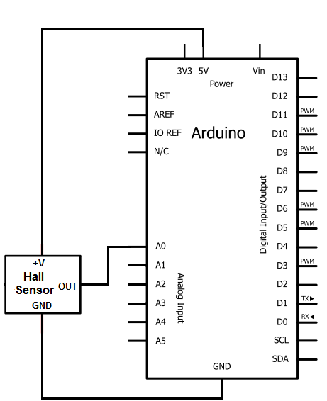
The Hall effect sensor utilized in this circuit is the A1302 Hall effect sensor manufactured by Allegro. This integrated circuit (IC) is capable of detecting magnetic fields. It will be connected to an Arduino, allowing the Arduino to read...
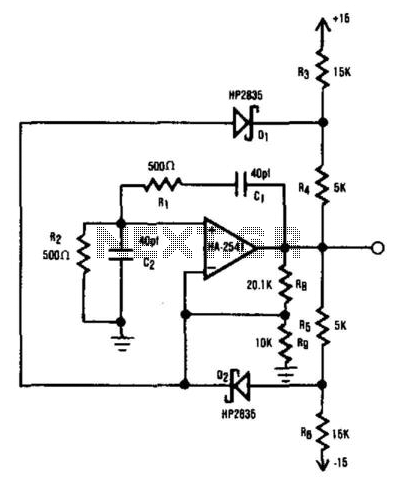
The HA2541 is ideal for use as the core component of an oscillator. Despite the basic diode limiting provided by R3 through R7 and D1 and D2, a high-quality sine wave at 40 MHz can be easily achieved, with...
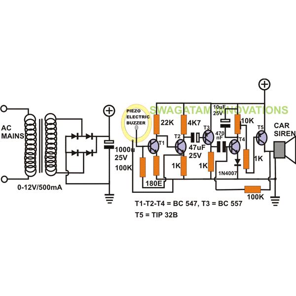
The project "DIY: Build a Sound Activated Switch" presented here is straightforward to construct and can be very useful in protecting a specific area from potential theft or intrusion. Learn how to build a simple sound-activated alarm here on...