
simple but reliable car battery tester
The LM3914 is a versatile LED bar graph/LED dot display driver that can be configured to display either a bar graph or a dot mode based on the connection of pin 9. In this circuit, the use of a high-impedance voltage divider is crucial, as it allows for accurate scaling of the car battery voltage to a level suitable for the LM3914’s internal comparators. The voltage divider typically consists of two resistors arranged in series, where the output voltage is taken from the junction of the two resistors. This configuration ensures that the voltage presented to the LM3914 does not exceed its maximum input rating while still providing a representative reading of the battery voltage.
The internal voltage regulation feature of the LM3914 simplifies the design by eliminating the need for an external regulator, thus reducing component count and potential points of failure. The stable output of 1.25V is critical for the accurate operation of the internal comparator network, which is responsible for determining the appropriate LED activation based on the input voltage.
The smoothing capacitor plays a significant role in stabilizing the voltage readings by filtering out transient spikes caused by the ignition system of the vehicle. This is particularly important in automotive applications, where electrical noise can lead to inaccurate voltage readings. The use of a 4700uF capacitor provides substantial filtering capability, ensuring that the circuit can deliver reliable performance even in the presence of electrical interference.
The ability to adjust the offset trimmer allows users to calibrate the circuit for different operational ranges. This flexibility is beneficial for users who may need to monitor battery voltages that fall below the typical operational range of 8V to 12V, enabling the circuit to function effectively across a broader spectrum of voltages.
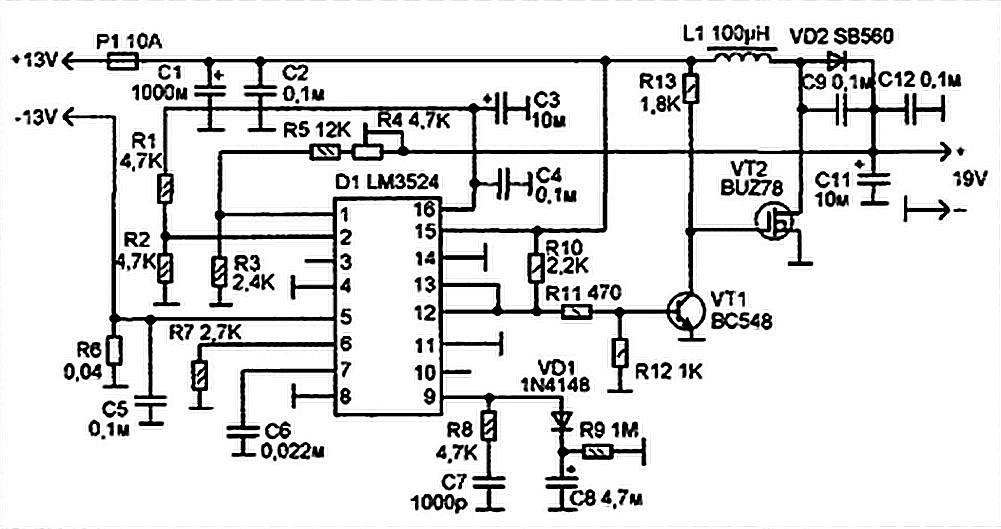
Overall, this circuit design offers a practical solution for monitoring car battery voltage with an emphasis on simplicity, reliability, and adaptability to various automotive conditions.This circuit uses the popular and easy to find LM3914 IC. This IC is very simple to drive, needs no voltage regulators (it has a built in voltage regulator) and can be powered from almost every source. This circuit is very easy to explain: When the test button is pressed, the Car battery voltage is feed into a high impedance voltage divider.
His p urpose is to divide 12V to 1, 25V (or lower values to lower values). This solution is better than letting the internal voltage regulator set the 12V sample voltage to be feed into the internal voltage divider simply because it cannot regulate 12V when the voltage drops lower (linear regulators only step down). Simply wiring with no adjust, the regulator provides stable 1, 25V which is fed into the precision internal resistor cascade to generate sample voltages for the internal comparators.
Anyway the default setting let you to measure voltages between 8 and 12V but you can measure even from 0V to 12V setting the offset trimmer to 0 (but i think that under 9 volt your car would not start). There is a smoothing capacitor (4700uF 16V) it is used to adsorb EMF noise produced from the ignition coil if you are measuring the battery during the engine working.
Diesel engines would not need it, but I`m not sure. If you like more a point graph rather than a bar graph simply disconnect pin 9 on the IC (MODE) from power. The calculations are simple (default) 🔗 External reference
Related Circuits
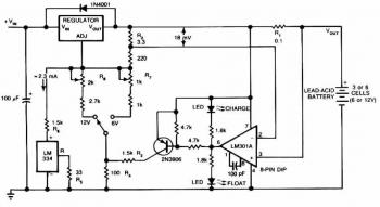
This circuit provides an initial voltage of 2.5 V per cell at 25°C to quickly charge the battery. As the battery charges, the charging current decreases, and when it drops to 180 mA, the charging circuit reduces the output...
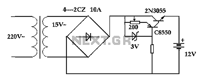
The circuit operates after a transformer, utilizing a bridge rectifier and conditioning for battery charging. The charging current transformer can be easily adjusted to provide approximately 12V at 100Ah battery charging. The required charging current is 10A, and a...
This design is based on one published by Milan Lulic in the German magazine elektroModell. Mr. Lulic's design is for surface mount technology (SMT) construction, whereas mine uses standard off-the-shelf components, and is therefore better suited to construction by...
Laptops, commonly referred to as notebook computers, have gained significant popularity. Their portable design allows them to be easily transported in a bag, making them suitable for business trips and serving as convenient home entertainment centers due to their...
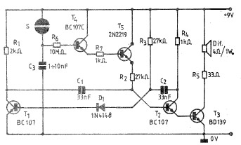
A simple and practical electronic bell circuit can be constructed using the provided schematic diagram. This circuit can function as a doorbell or an alarm system. It utilizes only a few transistors along with several common components. The circuit...
The car's small lamp and headlight can drain the battery if they are not turned off, leading to engine starting issues. A simple circuit, developed around 1980, can prevent this problem. It includes a series circuit with a diode...