
Simple Buzzer Using Only Passive Components

The novel buzzer circuit operates by employing a relay to control the flow of current to a small audio transformer, which in turn drives a speaker to produce sound. The relay serves as an electromechanical switch that opens and closes the circuit, allowing for the modulation of audio signals.
The circuit can be described as follows: When a control voltage is applied to the relay's coil, it energizes the relay, closing its normally open contacts. This action allows current to flow through the audio transformer. The transformer steps up or modifies the audio signal, which is then delivered to the speaker. The speaker converts the electrical energy into sound waves, producing the desired buzzing noise.
Key components of the circuit include the relay, which should be selected based on the required voltage and current ratings, ensuring it can handle the load of the audio transformer and speaker. The audio transformer should be chosen to match the impedance of the speaker for optimal sound quality. The speaker itself should have an appropriate power rating to handle the output from the transformer without distortion or damage.
In summary, this simple buzzer circuit effectively demonstrates the use of a relay in conjunction with an audio transformer and speaker to generate sound, making it suitable for various applications such as alarms, notifications, or simple sound effects in electronic projects. Proper selection of components and attention to circuit design will ensure reliable operation and sound performance.This circuit is a simple buzzer circuit and it called novel buzzer. It only uses a relay in series with a small audio transformer and speaker. The relay will. 🔗 External reference
Related Circuits
The address bits in the encoder are unconnected, while they are grounded in the decoder. It is advisable to connect them to ground in the encoder as well. Additionally, when the keys in the transmission circuit are open, the...
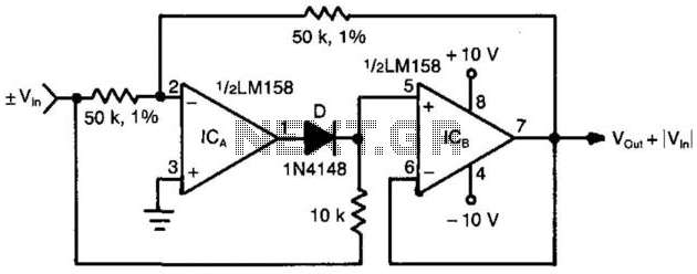
When the input voltage is positive, the output of ICA is negative, resulting in diode D not conducting; therefore, the output of ICB is positive. Conversely, when the input is negative, the output of ICA becomes positive. Diode D...

This post presents the implementation of a free-running counter using the C programming language for the PIC16F84A microcontroller. The code is structured to... The PIC16F84A microcontroller is a widely used device in various embedded applications, characterized by its 8-bit architecture...

Many consumer electronic devices such as television sets, VCRs, CD players, and DVD players utilize infrared remote control technology. In certain situations, it is beneficial to extend the range of these remote controls. Infrared (IR) remote controls operate by emitting...

A high-quality stereo FM transmitter circuit is presented here. The circuit utilizes the IC BA1404 from ROHM Semiconductors. The BA1404 is a monolithic FM stereo modulator that incorporates a built-in stereo modulator, FM modulator, and RF amplifier circuitry. The...
Amplifier circuit featuring a MOSFET output stage, serving as an alternative to the output stage that utilizes bipolar transistors. Advantages of the MOSFET amplifier include ease of operation, the ability to handle hundreds of watts with straightforward parallel configurations,...