
using RF modules with HT12e/d

To implement the described circuit effectively, it is necessary to ensure that the address bits of the encoder are properly connected to a defined logic level to avoid floating states that can lead to unpredictable behavior. Connecting these bits to ground will ensure that they are at a known low state when not actively driven by other signals.
Furthermore, when the transmission circuit keys are open, the input bits D0 to D3 should not be left floating. To mitigate this issue, pull-up resistors should be used. A pull-up resistor connected from each of these data lines to VCC (the positive supply voltage) will ensure that the input bits are held at a high logic level when the keys are open. The specified resistor value of at least 1k ohm is appropriate for most applications, providing a balance between power consumption and response time.
It is also crucial to ensure that the resistors used in both the encoder and decoder circuits are matched in value. Discrepancies in resistor values can lead to mismatched signal levels, which may result in communication errors between the encoder and decoder. Therefore, consulting the datasheet for recommended resistor values and tolerances is essential for maintaining signal integrity.
In summary, the circuit design should include proper grounding of the encoder's address bits, the implementation of pull-up resistors for the data lines, and the selection of matching resistors according to the specifications provided in the datasheet to ensure reliable operation of the encoder-decoder system.Your address bits in the encoder are floating, while those are connected to ground in the decoder. Do the same in the encoder also. Also note that when the keys in the transmission circuit are open, your input bits are floating, So pull up D0 to D3 of the encoder to VCC using a resistor not less than 1k. I hope you`ve selected matching resistors for the encoder and decoder, after going through the datasheet.
🔗 External reference
Related Circuits
Some time ago, a 1-key keyboard project was developed. The ATTiny microcontroller has been a recurring consideration since then. The 1-key keyboard project utilizes the ATTiny microcontroller, a compact and efficient device suitable for a variety of embedded systems applications....
This project Digital gated Emulator using Microcontroller is used to emulate the basic gates such us NOT, OR, AND. The system has the selector switch by which we can select any gate. The system has two inputs and one...

A simple circuit diagram illustrates a schematic for a remote control system, which consists of two components: a transmitter and a receiver. The transmitter circuit is controlled by the NE555 integrated circuit (IC). This system operates by detecting the...
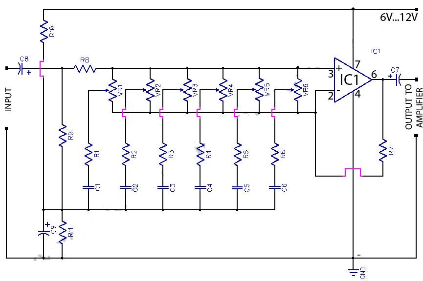
This circuit is a 6-band graphic equalizer that allows for the adjustment of low, medium, and high frequencies using the operational amplifier circuit 741. It enables control and mixing of frequencies and tones according to user preferences. The audible...
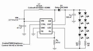
The schematic diagrams for the TPS61042 current LED driver illustrate its capability to power eight LEDs with an efficiency of 81% at 3.6V and 18.6mA. The TPS61042 is commonly utilized in applications such as white LED supply for backlight...
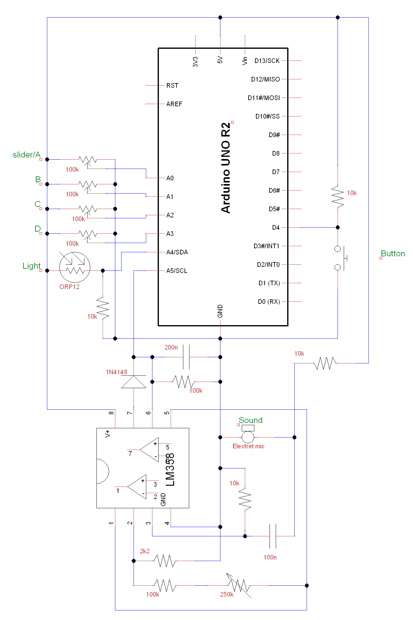
A circuit and Arduino code are designed to emulate a ScratchBoard approximately. The setup includes sound, light, a button, and four sliders, but it is not a direct replacement. It is important to change the COM ports in the...