
Simple CB transmitter with BD329

The circuit described is a basic AM transmitter that operates at a frequency of approximately 27 MHz. The essential components include a power supply, voltmeter, inductor, variable capacitor, and a microphone. The transmitter is powered by a +12V DC supply, with a current consumption expected to be between 0.7A to 1A, which indicates the power requirements for the operation of the circuit.
The inductor, labeled as L1/L2, is adjustable and plays a crucial role in tuning the transmitter to the desired frequency. The core of the inductor can be adjusted using a screwdriver, which changes the inductance and thus affects the frequency of emission. The variable capacitor, denoted as C6, is also adjustable and works in conjunction with the inductor to fine-tune the frequency. The goal is to achieve the highest possible amplitude modulation (AM) signal, which is indicated by the output observed on the voltmeter.
A 50W load is connected in place of the aerial, which is critical for proper signal transmission. The voltmeter is connected at the output to monitor the voltage levels, ensuring the transmitter operates within the desired parameters. During operation, when the microphone is connected and audio input is provided, the user should observe an increase in the reading on the multimeter, indicating successful modulation of the audio signal onto the carrier wave.
The expected output power of the transmitter is approximately 2.5W, which is suitable for short-range communication applications. If the setup is correct, the modulation depth should increase by approximately 30-35% when speaking into the microphone, demonstrating effective transmission of audio signals. This circuit can be used in various applications, including hobbyist projects, educational demonstrations, and basic communication systems.For the regulation it needs a voltmeter (with needle better) and charge 50W/5W. Connect charge 50W in the place of aerial, with the voltmeter in the exit voltmeter. Be supplied the transmitter with + 12V. It will be supposed we have consumption between 0,7-1A. With a screwdriver we regulate the core of inductor L1/L2 and later the variable C6 until we see the biggest tendency. We connect the microphone and speaking we observe the clue in the multimeter. If all have become right will be supposed the tendency, speaking, to go up roughly 30-35%. Tendency of catering: + 12V/1A DC. Frequency of emission at AM: ~27MHz. Force of expense: 2,5W 🔗 External reference
Related Circuits
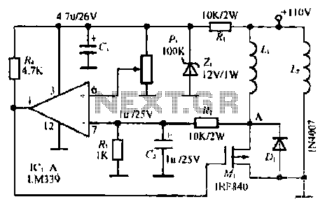
The LM339 comparator IC (Integrated Circuit) is utilized to enhance the functionality of electric circuits. A potentiometer (B) is incorporated to adjust the desired setpoint, while a feedback signal is generated by resistor (R). A significant pressure point is...
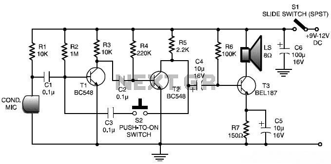
This is a low-cost and simple intercom circuit design. Some intercom circuits are built using integrated circuits. The circuit described here utilizes three readily available transistors that can be easily found in electronic stores. Even a novice can assemble...
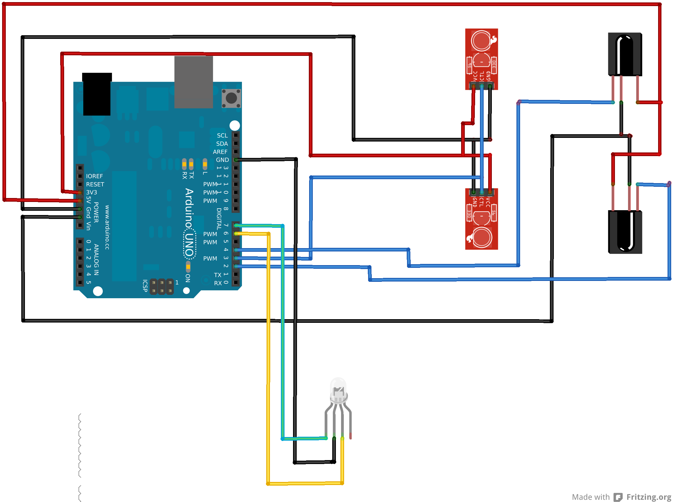
An Arduino Uno is connected to two infrared (IR) transmitters and their respective receivers. When one of the receivers detects a beam break, a strand of LEDs displays a pattern. While this setup functions correctly in principle, an issue...
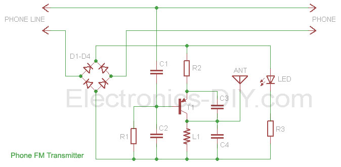
This phone FM transmitter connects in series to a telephone line and transmits telephone conversations over the FM band when the telephone handset is picked up. The transmitted signal can be tuned by any FM receiver. The circuit includes...
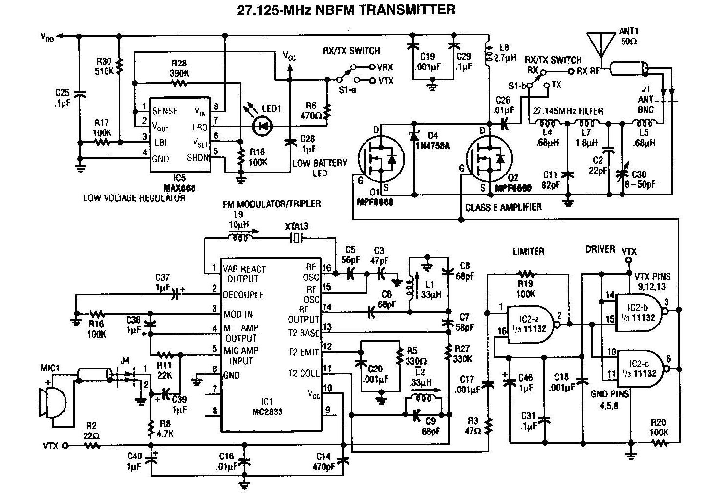
A 27MHz transmitter circuit schematic utilizing the MC2833 and two FET transistors, MPF6660. This design incorporates a Motorola MC2833 one-chip FM transmitter along with several supporting components. The 27MHz transmitter circuit is designed to operate within the FM radio frequency...

The hardware design for USB is quite minimal, which is advantageous. However, it quickly becomes apparent that the simplicity of the hardware design leads to complex communication and control software, which will be explored further in the theory and...