
SIMPLE CONTINUITY TESTER CIRCUIT
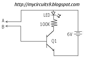
This simple continuity tester circuit is designed to provide an efficient means of verifying the integrity of electronic components and circuits. The circuit typically consists of a power source, an LED indicator, and a series of resistors to limit current and protect the LED from excessive current flow.
When testing a component, the user connects the terminals A and B to the leads of the component or circuit segment. The power source energizes the circuit, and if a continuous path is present, current flows through the LED, causing it to light up. The brightness of the LED can indicate the quality of the connection; a dim LED may suggest a high-resistance connection, while a bright LED indicates a low-resistance path.
In applications involving high impedance components, the circuit may incorporate a buffer stage or an operational amplifier to ensure that the testing process does not affect the component being tested. This is crucial for components like capacitors and transformers, where the testing circuit should not influence the component's behavior.
Overall, this simple continuity tester is an invaluable tool for electronics repair, allowing technicians to quickly diagnose faults and determine the operational status of various electronic components without the limitations imposed by traditional multimeters.This circuit have an advantage over ordinary CONTINUITY testing Device, usually we are using multimeter to check the continuity of a circuit. It is not suitable to check the continuity of a circuit with high Impedence or resistance like Transformer, Capacitors, and even for high value Resistors.
This circuit helps you to determine whether the devi ce or electronic component is working fine And by using this SIMPLE CONTINUITY TESTER you can repair any damaged electronic devices easily [By identifying the actual fault of the device]. Connect the terminals A and B to any electronic component or circuit which is to be tested. The LED will glow if the circuit having a continuous path or the component is working finely. Otherwise the LED remains OFF. 🔗 External reference
Related Circuits
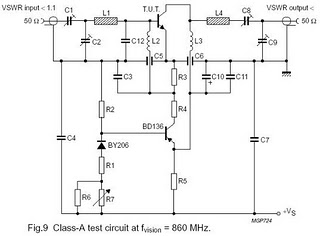
The circuit is designed for driving small UHF TV transmitters, providing a gain of 7 dB and capable of amplifying signals within the frequency range of 470-860 MHz. Key components include resistors, capacitors, and transistors. This circuit serves as a...
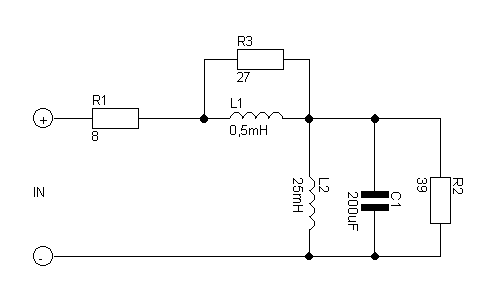
If you want to test an amplifier, a dummy load may be more convenient for speakers to use than actual speakers, due to noise or damage to the speakers. This circuit behaves in terms of impedance and frequency response...
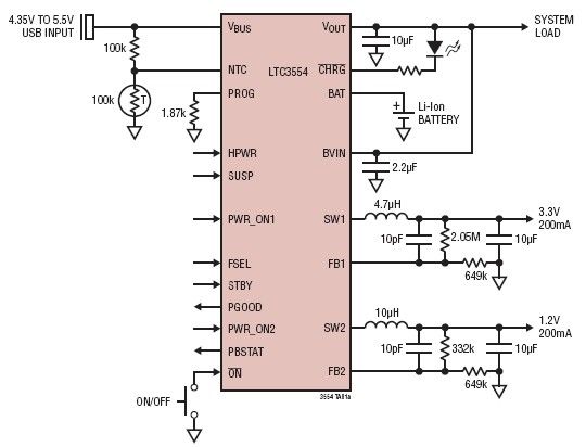
This micropower multifunction power management integrated circuit (PMIC) is designed using the LTC3554, manufactured by Linear Technology Corporation. It serves as a solution for portable Li-Ion Polymer battery-based applications. The LTC3554 integrates a USB-compatible linear PowerPath manager, a standalone...
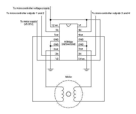
A stepper motor is a motor controlled by a series of electromagnetic coils. The center shaft has a series of magnets mounted on it, and the coils surrounding the shaft are alternately energized or de-energized, creating magnetic fields that...
An increasing number of appliances draw a very small current from the power supply. When designing a mains-powered device, one can typically choose between a linear power supply and a switch-mode power supply. However, if the total power consumption...

This is a simple design for a voltage regulator circuit using a pass transistor. The design is built around the LM317T. The output current of the LM317T can be increased by incorporating an additional power transistor to share a...