
TV RF Amplifier 5W Circuit With BLW98

This circuit serves as a critical amplifier stage in UHF TV transmitter applications, enhancing the strength of received signals to ensure optimal transmission quality. The gain of 7 dB indicates that the circuit effectively increases the power level of the input signal, making it suitable for broadcasting within the specified frequency range of 470-860 MHz.
The design typically incorporates a combination of resistors, capacitors, and transistors. Resistors are employed to set the biasing conditions for the transistors, ensuring they operate efficiently in the active region. Capacitors may be used for coupling and decoupling purposes, allowing AC signals to pass while blocking DC components, thus maintaining signal integrity.
Transistors, which are the primary active components in this circuit, function as the amplifying devices. Depending on the specific design, different transistor types (such as BJTs or FETs) can be utilized to achieve the desired performance characteristics. The choice of transistors will influence the overall efficiency, linearity, and thermal stability of the amplifier.
Additional considerations in the design include impedance matching to ensure maximum power transfer from the source to the load, as well as filtering components to minimize unwanted harmonics and noise. The overall layout of the circuit is crucial in minimizing parasitic capacitances and inductances, which can adversely affect performance at UHF frequencies.
In summary, this circuit is an essential component in enhancing UHF TV transmission, utilizing a well-thought-out arrangement of resistors, capacitors, and transistors to achieve a reliable gain and effective signal amplification.Function: for driving small UHF TV transmitters, with gain is 7dB and can amplify a signal between 470-860 MHz. Component: Resistor, Capacitor, Transistor, .. 🔗 External reference
Related Circuits
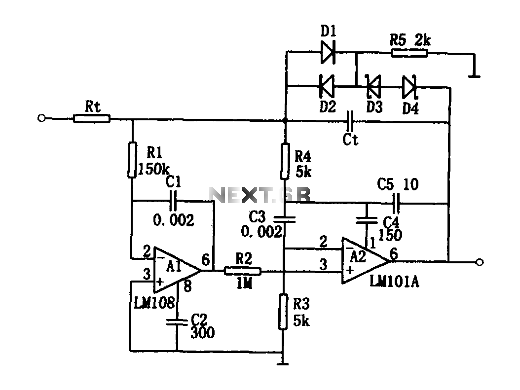
The high-speed integrating circuit is designed with an integration time constant circuit, RtCt, which offers a wide range. When the integrating capacitor Ct is not considered, A2 functions as a positive feedback compensation broadband AC amplifier. The negative feedback...
This circuit features an adjustable output timer capable of re-triggering at specified intervals. The output duration can range from a fraction of a second to over half an hour, with the ability to recur at regular intervals spanning from...
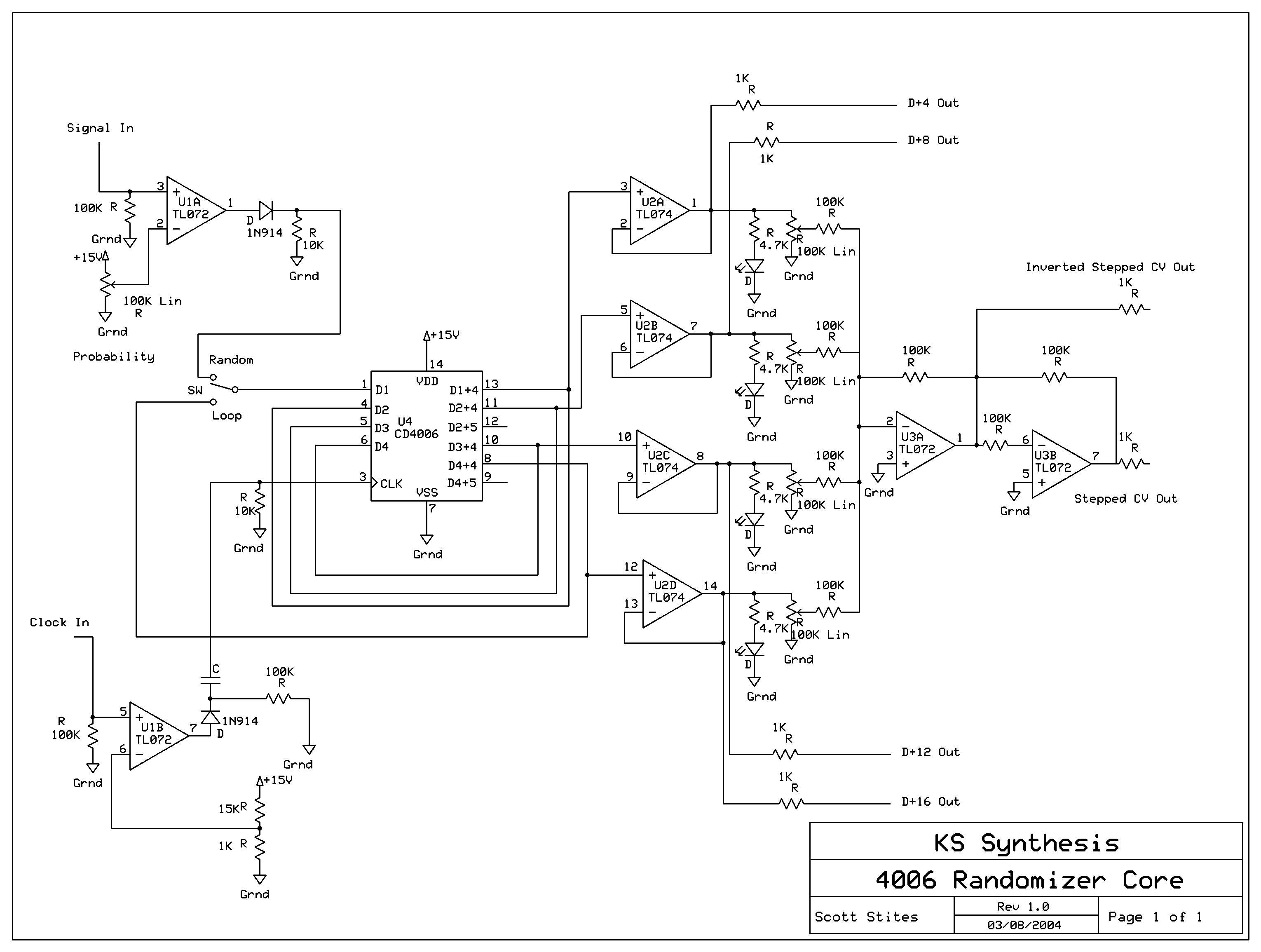
The mechanics of the Quantized Random Voltage function are intriguing. Instead of having fixed quantization steps for each output of the 4006 shift register, it is proposed to make the voltages adjustable through potentiometers. The Quantized Random Voltage function...
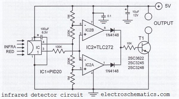
This infrared detector circuit utilizes a passive infrared detector component, PID20, which converts heat radiation into electrical impulses. The output voltage of the PID20 increases when an object approaches, provided that the object is warmer than the surrounding environment....
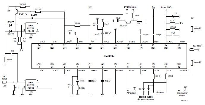
The integrated circuit (IC) is a multistandard vision and sound intermediate frequency (IF) phase-locked loop (PLL) demodulator that operates without the need for alignment. It supports multiple standards, including PAL, SECAM, and NTSC, and is capable of processing both...
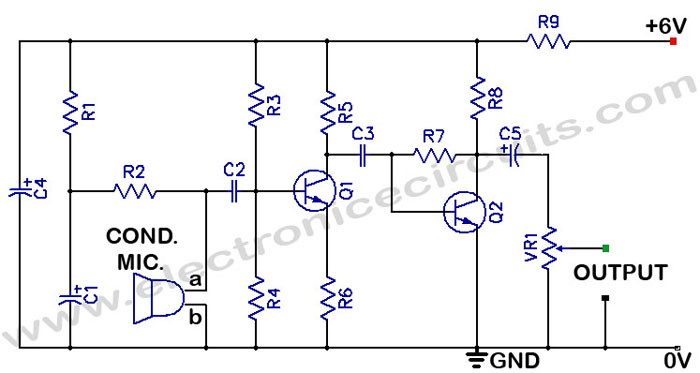
There is often a need for a sensitive sound pickup device, which can be utilized as a simple microphone or for more specialized applications such as a sound-operated alarm, a bugging device, or a sound-triggered flash for stop-action photography....