
simple current controlled led tube

The circuit operates on the principle of feedback control, where the current flowing through the LEDs is monitored and regulated to prevent damage due to overcurrent conditions. The high-voltage transistors, T1 and T2, play critical roles in this regulation process. T1 is primarily responsible for conducting the current to the LEDs, while T2 serves as a protective switch that activates under conditions of excessive current.
The resistor R2 is a crucial component in this circuit, as it not only converts current to voltage but also provides the necessary feedback to control T1. The choice of R2's resistance value is critical; it must be calculated based on the expected maximum current through the LEDs to ensure that it can effectively sense the overcurrent condition without allowing excessive voltage drop under normal operating conditions.
Capacitor C1 is utilized for filtering and stabilizing the input AC signal, providing a smoother and lower-level current that is suitable for the operation of the transistors and LEDs. Its value must be selected to balance the response time and the filtering characteristics, ensuring that transient voltage spikes do not adversely affect the circuit operation.
Overall, this current-controlled LED tube light circuit demonstrates a robust design for managing LED operation, ensuring longevity and reliability through effective current regulation. The combination of feedback mechanisms and protective components allows for safe operation across varying input conditions, making it suitable for applications where LED longevity is paramount.The given circuit of a current controlled LED tube light uses a couple of high voltage transistors which works on a very basic principle for implementing the required current control operation. Resistor R2 is placed forconvertingthe rising current to voltage across itself. This voltage is sensed by R2 which immediately conducts and grounds T1s base rendering it inactive, the instantaneous processinitiatesa switching effect, producing the desired current control and safeguarding of the LEDs. Each channel consists of 50 white LEDs in series. R2 is calculated with the following formula: When input AC is applied to the circuit, C1 drops the input current down to a lower level which can be considered to be safe for operating the involved electronic circuit.
As long as the current delivered by T1 or rather current drawn by the LEDs iswithinthe specified safe limit, T2 remains in a non-conducting state, however of the current drawn by the LEDsbeginsto cross the safe limit, the voltage across the limiting resistor R2 begins to develop a small voltage across it. This inhibits T1 from conducting fully and its collector current stops rising any further. Since the LEDs form the collector load of T1, the current through the LEDs also gets restricted and the devices are safeguarded from the rising current intake.
Ths above rise in the current takes place when the input AC rises, producing an equivalent increase in the LED current consumption, but the inclusion of T1 and T2, ensures thatanythingthat`s dangerous to the LEDs iseffectivelycontrolled and curbed. 🔗 External reference
Related Circuits
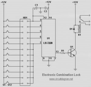
This circuit diagram represents a simple electronic combination lock utilizing the IC LS7220. The circuit is designed to activate a relay for controlling any device (on and off) each time a specific combination of four digits is entered. It...
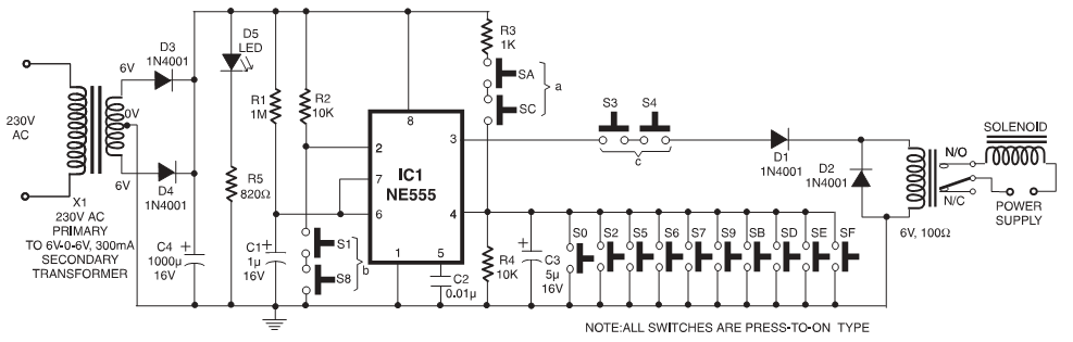
In these circuits, a set of switches (conforming to code) are pressed sequentially within a specified time to unlock the mechanism. In some configurations, custom-built integrated circuits (ICs) are utilized, and positive and negative logic pulses are input in...
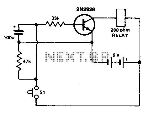
Press SI. The 100 µF electrolytic capacitor rapidly charges up from approximately 0 V. The transistor becomes forward biased, allowing collector current to flow and operate the relay. When SI is released, the capacitor discharges through the 33 K...
This site serves as a collection of useful information that the author wishes to retain, with the occasional inclusion of pages that may be of interest to others. The author has documented the retrofit of the Boxford 125 TCL...
This relatively simple mixer was designed for three dynamic microphones, but can be re-designed for more or less. Level and tone controls are available to tailor the sound to your needs. More: R1-R3 are level controls. R9 and R11...
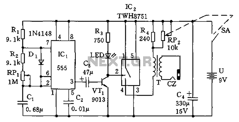
The circuit is composed of a 555 oscillator and an amplifier driver stage. It includes the 555 timer along with resistors R1, R2, RP1, capacitor C1, and other components forming a multi-harmonic oscillator. The frequency can be adjusted using...