
Simple Current Feedback Power Amplifier

Expanding on the original description, the schematic in Figure 1 illustrates an audio amplifier circuit with a speaker coupling capacitor. The speaker coupling capacitor connects the output of the amplifier to the speaker, blocking any DC component of the signal and allowing only the AC component to pass.
In the original designs from the referenced era, a 1000uF capacitor was commonly used. This capacitor value provides a -3dB frequency response at 20Hz for an 8 Ohm load, which is a standard impedance for many speakers. However, this value is considered too small for optimal performance.
The circuit shown in Figure 1 uses a 2200uF capacitor instead. This value is still marginal, as it may not provide the best low-frequency response. A larger capacitor, such as 4700uF, would offer a lower -3dB frequency and hence better bass response.
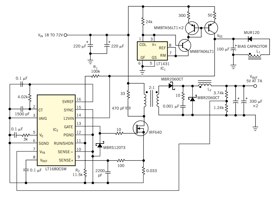
However, increasing the capacitor value beyond this point may not be cost-effective. Larger capacitors are more expensive and could make the amplifier less affordable, defeating the purpose of designing a cost-effective amplifier. Therefore, a balance must be struck between achieving optimal performance and maintaining affordability. The choice of capacitor value will depend on the specific requirements of the audio system and the budget constraints.Figure 1 shows the circuit. A major change from all of the designs from that era is the speaker coupling capacitor - 1000uF (for a -3dB of 20Hz and a 8 Ohm load) was the most common value. This is too small, and the 2200uF shown is actually marginal. 4700uF would be better, or even more - but that would defeat the purpose, since the amp would no longer be cheap.
🔗 External reference
Related Circuits
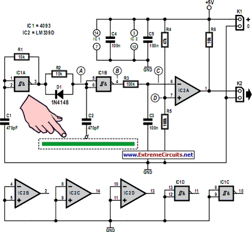
A battery-powered, pushbutton-triggered TTL/CMOS-compatible source of debounced 5V logic pulses is a simple but handy piece of test equipment to have in any tool kit. The circuit's battery-powered operation complicates what would otherwise be a trivial exercise in switch-bounce...
Capacitive touch sensors operate based on the electrical capacitance of the human body. When a finger approaches the sensor, it establishes a capacitance to Earth ranging from 30 to 100 pF. This phenomenon can be utilized for proximity detection...
This little circuit can be used to dim lights up to about 350 watts. It uses a simple, standard TRIAC circuit that, in my experience, generates very little heat. Please note that this circuit cannot be used with fluorescent...
The objective of this project was to monitor power consumption in a residential setting. In addition to tracking total usage, the goal was to separately monitor and compare the usage of major appliances, such as the water heater, heat...
Construct a variable 5A, 2V to 25V regulated power supply using the LM338 adjustable regulator. A power supply schematic and parts list are provided here. The LM338 adjustable voltage regulator is a versatile component capable of providing a regulated output...
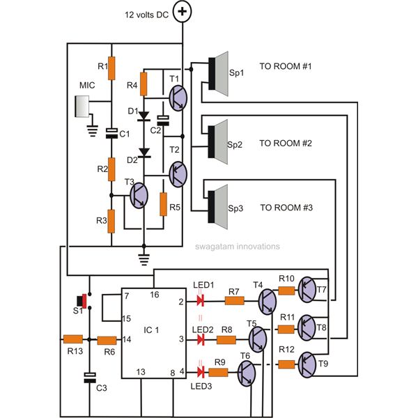
A home intercom system can be constructed using a versatile circuit design. This system allows communication across up to ten different locations or rooms discreetly. It utilizes a single changeover switch for selecting the desired location, replacing the traditional...