
2V-25V DC Power Supply Schematic

The LM338 adjustable voltage regulator is a versatile component capable of providing a regulated output voltage ranging from 1.25V to 37V with a maximum output current of 5A. To construct a variable power supply utilizing the LM338, the following components are typically required: the LM338 regulator itself, resistors for setting the output voltage, capacitors for input and output stabilization, a heat sink for thermal management, and a suitable transformer or power source.
The schematic for the power supply begins with the AC input, which is typically stepped down using a transformer. The output of the transformer is rectified using a bridge rectifier composed of four diodes, converting the AC voltage to a pulsating DC voltage. This pulsating DC voltage is then filtered using large electrolytic capacitors to smooth out the ripples, providing a more stable DC input to the LM338.
The LM338 requires two resistors to set the output voltage. By connecting a variable resistor (potentiometer) in series with a fixed resistor, the output voltage can be adjusted from 2V to 25V. The formula for the output voltage (Vout) is given by Vout = 1.25V * (1 + R2/R1), where R1 is the resistor connected from the output to the adjust pin, and R2 is the resistor connected from the adjust pin to ground.
To ensure stability and performance, it is crucial to include bypass capacitors at both the input and output terminals of the LM338. A 0.1µF ceramic capacitor is typically placed close to the output pin to filter high-frequency noise, while a larger electrolytic capacitor (e.g., 10µF) may be used at the input to improve transient response.
Thermal management is also an important consideration. The LM338 can dissipate significant heat, especially at higher output currents. Therefore, a suitable heat sink must be attached to the regulator to prevent thermal shutdown during operation.
Finally, a voltmeter and ammeter can be added to the output for monitoring the voltage and current supplied to the load, enhancing the usability of the power supply. The entire assembly should be housed in a suitable enclosure to ensure safety and protect the components from damage.Construct a variable 5A, 2V to 25V Regulated Power Supply using LM338 Adjustable Regulator. Power supply schematic and parts list is provided here .. 🔗 External reference
Related Circuits
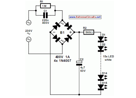
An array of white LEDs can serve as an effective small lamp for the living room. LED lamps are commercially available. LED arrays are increasingly popular for providing ambient lighting in residential spaces. The use of white LEDs in a...
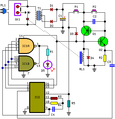
Q1 and Q2 create an ALL-ON ALL-OFF circuit that, when in the off state, draws negligible current. P1 initiates the circuit, activating the relay and powering the two integrated circuits (ICs). The lamp is energized through the relay switch,...
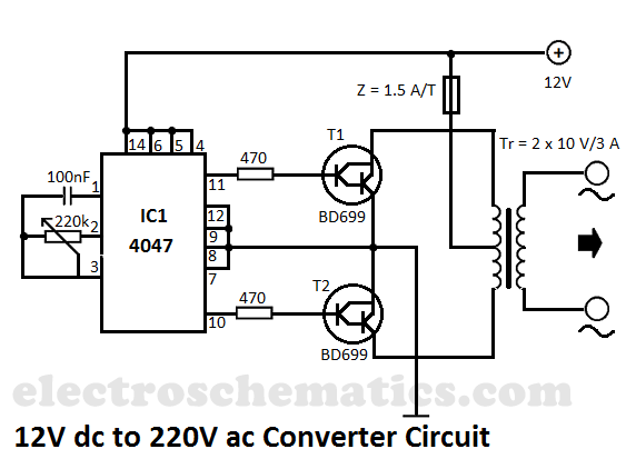
This DIY 12V to 220V voltage converter is built with the CMOS 4047, which serves as the main component of this compact voltage converter that transforms 12V DC into 220V AC. The 4047 is configured as an astable multivibrator,...
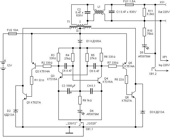
220 watts Uninterruptible Power Supply. Refer to the designated page for an explanation of the related circuit diagram for this power supply. The 220 watts Uninterruptible Power Supply (UPS) is designed to provide reliable backup power during outages, ensuring that...
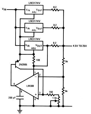
The LM317HV adjustable regulator is capable of supplying over 1.5A across an output voltage range of 1.2V to 57V. The design of this high current power supply is straightforward, as the LM317HV requires only a few external resistors to...
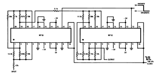
Later, there will be applications including a Basic Circuit Description, Block Diagram of the MF10, Programmable Dual Clock Generator, Butterworth Lowpass Filter, MF10 as an Input Filter and Sample/Hold, Generating Quadrature Sine Waves, and the Non-Inverting Integrator used in...