
Simple Electronic Combination Lock

The electronic combination lock circuit primarily operates based on the LS7220 integrated circuit, which is designed for security applications requiring a coded input to unlock a mechanism. The LS7220 is a highly integrated device that provides the necessary logic to interpret the key sequence entered by the user.
The capacitor C1 (1µF, 25V) serves as a coupling capacitor, filtering out any noise from the power supply and ensuring stable operation of the IC. Capacitor C2 (220µF, 25V) acts as a decoupling capacitor, providing additional stability and energy storage for the circuit during operation.
Resistor R1 (2.2K Ohm) is used to limit the current flowing into the base of the transistor Q1 (either 2N3904 or 2N2222), which functions as a switch to control the relay K1. The choice of transistor allows for sufficient current amplification, enabling the relay to activate without overloading the IC.
Diode D1 (either 1N4148 or 1N4001-1N4007) is included to protect the circuit from back EMF generated when the relay coil is de-energized. This diode is connected in reverse bias across the relay coil terminals, ensuring that any voltage spike is safely redirected away from the sensitive components of the circuit.
The relay K1 (12V SPDT) serves as the actuating mechanism for the lock, allowing it to control a locking mechanism or other devices requiring a switchable action. The relay can be replaced with any appropriate alternative that meets the voltage and current specifications required by the application.
Overall, this combination lock circuit is designed for simplicity and effectiveness, making it suitable for various security applications where electronic access control is needed.The following diagram is a very easy and simple electronic combination lock based on IC LS7220. Component Part List: C1 = 1uF 25V C2 = 220uF 25V R1 = 2.2K Ohm Q1 = 2N3904 / 2N2222 D1 = 1N4148 / 1N4001-1N4007 K1 = 12V SPDT Relay / Any approp.. 🔗 External reference
Related Circuits
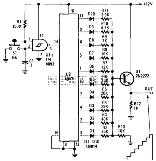
U2 is a decade counter/divider, U1 is used as a switch debouncer. For a self-generating system, connect a resistor between pins 2 and 3 of U1, value that should be between 10 KOhm and several, depending on desired frequency....
A modified Hartley oscillator can be utilized to attract new friends or serve as a replacement doorbell. The modified Hartley oscillator is a type of LC oscillator that uses an inductor-capacitor (LC) circuit to generate a continuous wave signal. This...
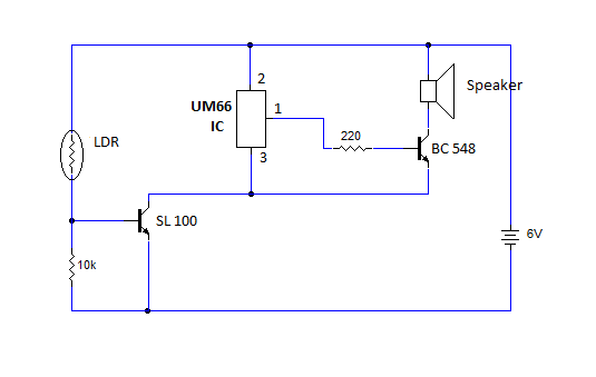
This article provides instructions for creating a light-sensitive morning alarm circuit. The circuit utilizes an LDR (Light Dependent Resistor) or photoresistor to detect morning light, which triggers the alarm section. When light is detected, the circuit produces a melodious...
This precise one-pulse-per-second clock is constructed using a few common components and is driven by a 50 or 60 Hertz mains supply without any direct connection to it. A beep or a metronome-like click, along with a visible flash,...
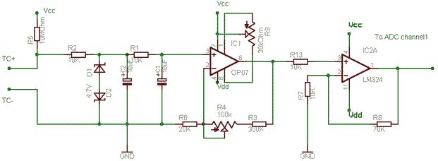
The OP07 operates as a non-inverting amplifier to avoid loading the millivolt signal from the thermocouple. Zener diodes are included to protect the circuit in the event of a failure in the junction contacts, heaters, or ground. A resistor-capacitor...
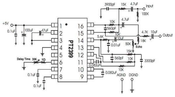
A single-chip circuit for echo and delay. If a microphone mixer circuit can be modified, this circuit can be easily used with a microphone. The PT2399 is an echo audio processor integrated circuit (IC) that utilizes CMOS technology and...