
Simple Electronic Metronome

The metronome circuit typically consists of a few key components: a timer IC (such as the 555 timer), resistors, capacitors, a speaker or piezo buzzer, and a power supply. The 555 timer is configured in astable mode, generating a square wave output at a frequency determined by the values of the resistors and capacitors connected to it. This frequency corresponds to the desired beats per minute (BPM) for the metronome.
To construct the circuit, the following steps are generally followed:
1. **Power Supply**: The circuit is powered by a DC supply, usually between 5V and 15V, depending on the specifications of the timer IC and the output device.
2. **Timer Configuration**: The 555 timer is connected in astable mode. Two resistors (R1 and R2) and a capacitor (C1) are connected to the timer to set the frequency of oscillation. The frequency (f) can be calculated using the formula:
\[
f = \frac{1.44}{(R1 + 2R2) \cdot C1}
\]
Adjusting R1, R2, and C1 allows for modification of the tempo.
3. **Output Stage**: The output pin of the 555 timer is connected to a speaker or piezo buzzer. The output can be amplified with a transistor if needed, especially if a louder sound is desired.
4. **User Controls**: Additional controls can be incorporated, such as a potentiometer to allow for fine-tuning of the tempo, and a switch to turn the metronome on and off.
5. **Enclosure**: The circuit can be housed in a small enclosure with a user interface that includes a tempo display, control knobs, and an on/off switch.
This metronome circuit is not only a practical tool for musicians but also serves as an excellent project for those looking to understand basic electronic components and their interactions.Metronome is an electronic device that keeps rhythm by making regulated clicking sounds, device used to keep the beat while playing a musical instrument. The circuit is an old design to build, but you will find it useful. 🔗 External reference
Related Circuits
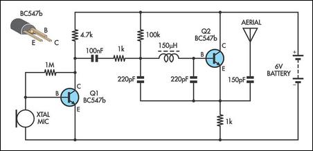
This AM transmitter is notably simple to construct due to its design, which features a non-tapped inductor with a single winding. The inductor is not custom-wound, as it can be sourced from readily available RF chokes, such as the...
A simple thermostat circuit that can control a relay to supply power to a small space heater through the relay contacts. The relay contacts must be rated above the current requirements for the heater. Temperature changes are detected by...
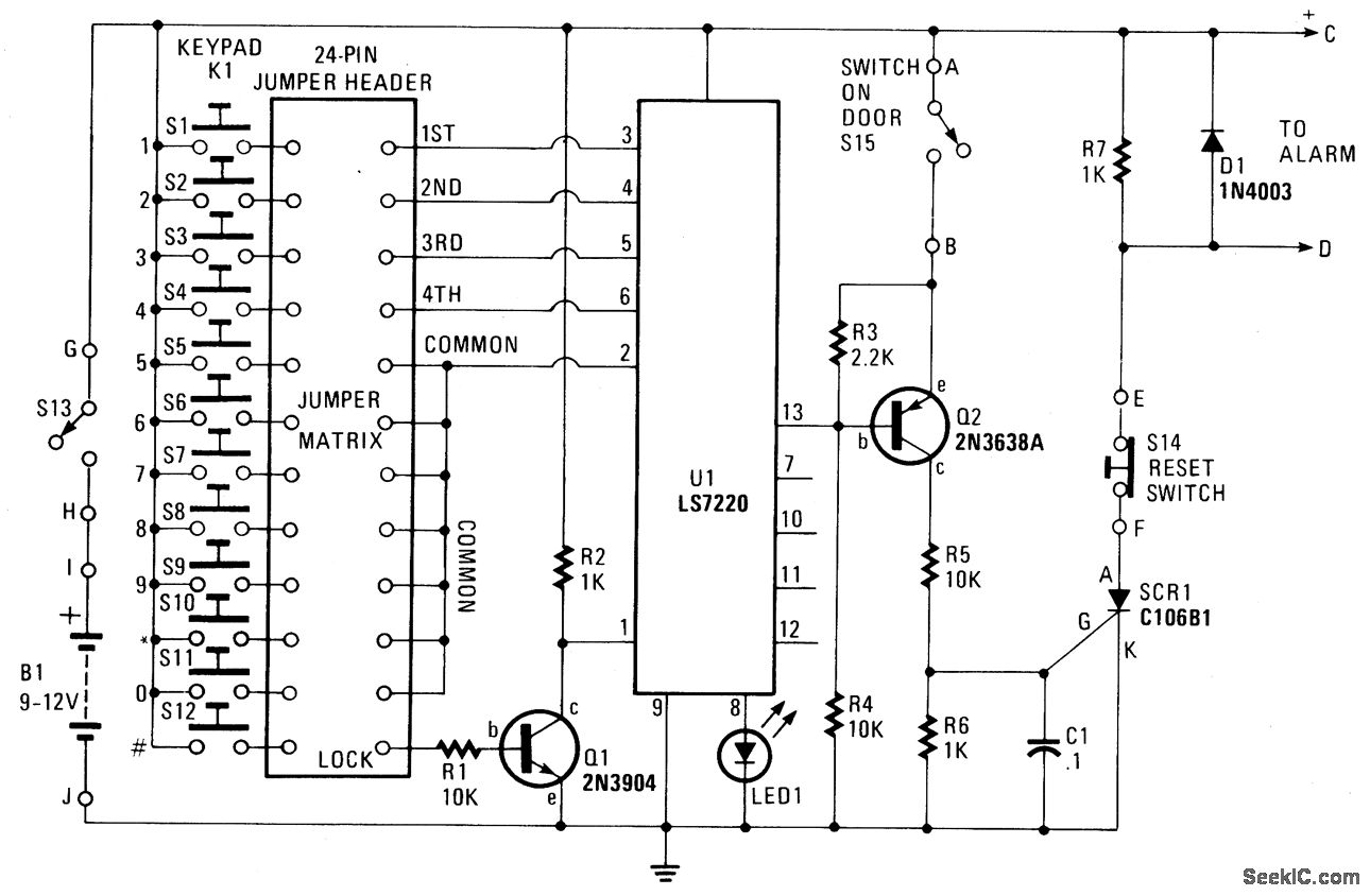
When button S12 is pressed, a positive voltage supplied through resistor R1 is applied to the base of transistor Q1, activating it. When Q1 is in the conducting state, pin 1 of U1 is connected to ground (low) or...

This is a simple AVR programmer designed for Atmel microcontrollers from the AVR family that support serial programming. The programmer connects to a PC via the RS232 serial interface and is compatible with PonyProg or Avrdude software. It is...

Writing about multiple circuits in Marx, an entire new set has been discovered, referred to as "the" Marx Generator. There are diagrams available, along with a useful quote: "The main advantage of the Marx circuit configuration over a more...
The circuit functions as a random number generator, producing numbers from 1 to 6. It features a line of LEDs, each corresponding to a number in the range of 1 to 6. When the push button S1 is pressed...