
Electronic Dice circuit

The circuit design employs a microcontroller or a dedicated random number generator IC to produce random values in the specified range. The push button S1 serves as the input mechanism for user interaction, triggering the generation of a random number upon being pressed.
Each of the six LEDs is connected to a digital output pin of the microcontroller, and a current-limiting resistor is used in series with each LED to prevent excessive current flow, ensuring their longevity. The microcontroller is programmed to generate a random integer between 1 and 6 when the button is pressed. The corresponding LED for the generated number is then activated.
The timing for the LED illumination is controlled by a delay function in the microcontroller's firmware, which allows the selected LED to remain lit for a predetermined period of five to ten seconds. After this time elapses, the microcontroller switches off the LED and resets the system, preparing for the next button press.
Power supply considerations are essential; the circuit can be powered by a standard battery or a DC power source, ensuring the voltage levels are suitable for the microcontroller and LED operation. Proper grounding and decoupling capacitors may also be included to enhance circuit stability and performance.
In summary, this random number generator circuit effectively simulates the randomness of dice rolls using a simple user interface and visual feedback through LEDs, making it suitable for various applications, including games and educational tools.The particular circuit is substantially a generator of accidental numbers, from 1 until the 6. The clue him we see in a line from led, that each one corresponds also in a number from the 1-6, if push and leave, the S1 (push button). This movement corresponds in a movement of dice. The led that it turned on will remain turned on for five until ten seconds and afterwards it will black out, waiting for the next movement..
🔗 External reference
Related Circuits
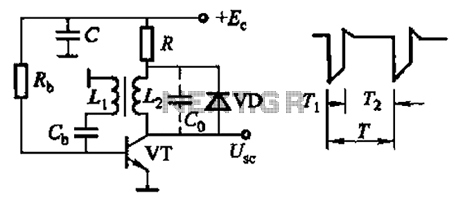
Common non-sinusoidal oscillator circuit, waveform and frequency formula - sawtooth oscillator - use blocking oscillator The sawtooth oscillator is a type of non-sinusoidal oscillator that generates a waveform characterized by a linear rise in voltage followed by a rapid drop....
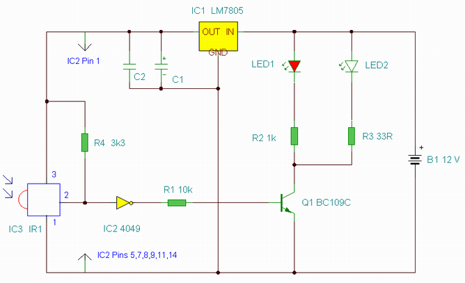
This is an enhanced infrared (IR) remote control extender circuit. It features high noise immunity, resistance to ambient and reflected light, and an increased operational range. The improved IR remote control extender circuit is designed to extend the range of...
This project involves a 555 buzzer circuit utilizing the NE555 timer IC, which comes in an 8-pin DIP package and performs a wide variety of functions in electronic circuits. The circuit described will produce a buzzer sound when a...
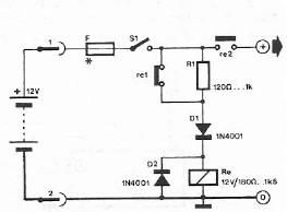
Safety polarity connection circuit design using common electronic components The safety polarity connection circuit is designed to ensure that electronic devices are connected with the correct polarity, preventing damage from reversed connections. This circuit typically employs common electronic components such...

FIG IC, ICR, Ri, R, and AN composition form a bistable contact circuit with a Ge transistor. It includes components such as ICc, lc, c2, and Dj, and is associated with a one-shot delay circuit. The circuit can be...
The astable multivibrator circuit lacks a stable state. In the absence of an external signal, the internal transistors alternately switch between cutoff and saturation at a frequency determined by the RC time constants of the coupling circuits. Therefore, an...