
Simple High-Pass (Hp) Active Filter For 1Khz Circuit
 Active Filter For 1Khz")
The described circuit consists of a basic low-pass filter configuration, which is essential for applications that require the attenuation of high-frequency signals while allowing lower frequencies to pass through. The filter operates at a nominal frequency of 1 kHz, making it suitable for audio frequency applications.
The voltage follower, often implemented using an operational amplifier (op-amp), serves to buffer the output of the RC filter. This configuration ensures that the filter does not load the previous stage, thereby maintaining signal integrity. The op-amp is connected in a non-inverting configuration, where the output directly connects to the inverting input, providing high input impedance and low output impedance.
The RC section consists of a resistor (Rl) and a capacitor (Cv) arranged in series, with the output taken across the capacitor. The cutoff frequency (f_c) is defined by the equation f_c = 1/(2πRlCv). For a cutoff frequency of 1 kHz, specific values for the resistor and capacitor can be selected to achieve the desired performance. Adjusting these components allows the designer to tailor the filter for various applications and frequency ranges.
The filter's response characteristics indicate that for frequencies above the cutoff, the output signal attenuates at a rate of 6 dB per octave, which corresponds to a doubling of frequency resulting in a decrease in output voltage. This gradual roll-off is beneficial in many audio processing applications, where it is essential to minimize unwanted high-frequency noise while preserving the integrity of the desired audio signal.
In summary, this 1 kHz filter design using a voltage follower and RC components is a fundamental circuit that provides effective low-pass filtering characteristics, with flexibility in frequency response adjustment based on component selection. This simple 1 kHz filter uses a voltage follower and an RC section for a.filtcr element. For other frequencies /3 dB - 1/6.28 RlCv The response drops 6 dB/octave below/- dB.
Related Circuits
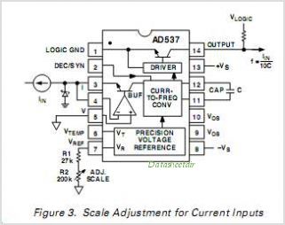
The AD650 is a voltage-to-frequency (V/F) and frequency-to-voltage (F/V) converter that offers high-frequency operation and low nonlinearity, features that were previously unavailable in a monolithic form. Its inherent monotonicity in the V/F transfer function makes the AD650 suitable for...
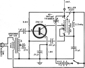
It had been a little over a decade since the invention of the transistor when this article appeared in the August 1959 edition of Popular Electronics. Transistors were still a mystery to many, including engineers, technicians, and hobbyists. Author...
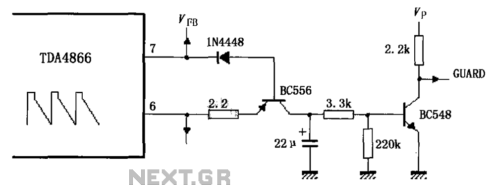
As illustrated in FIG TDA4866, the circuit consists of an external signal generator circuit protection. The internal protection circuit's role is to manage control, while the external protection circuit performs its functions. During normal operation, the vertical amplitude of...
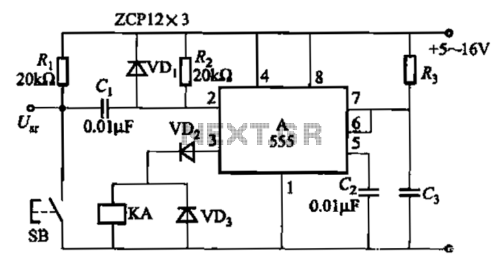
The 555 integrated circuit is utilized in a delay circuit configuration, functioning as a one-shot timer. The delay time can be adjusted using resistor R3 and capacitor C3. Typical values for R3 range from 1 kΩ to 10 MΩ,...
The circuit employs a widely used Sharp IR module (the Vishay module may also be utilized). The pin numbers indicated in the circuit pertain to both the Sharp and Vishay modules. For other modules, it is recommended to consult...
This is a power-on time delay relay circuit that utilizes the emitter/base breakdown voltage of a standard bipolar transistor. The reverse-connected emitter/base junction of a 2N3904 transistor functions as an 8-volt zener diode, establishing a higher turn-on voltage for...