
555 IC using a delay circuit 2

The 555 timer IC is a versatile component widely used in various timing applications. In its one-shot configuration, the 555 timer generates a single output pulse in response to a triggering event. The duration of this pulse is determined by the values of the timing resistor (R3) and the timing capacitor (C3).
When the circuit is triggered, the capacitor C3 begins to charge through the resistor R3. The charging time is governed by the time constant τ, which is defined as τ = R3 × C3. The voltage across the capacitor rises exponentially until it reaches approximately 2/3 of the supply voltage (Vs), at which point the output of the 555 timer transitions from a low state to a high state. The output remains high until the capacitor is fully discharged, at which point the output returns to its low state.
For precise timing applications, selecting appropriate values for R3 and C3 is crucial. For instance, using R3 at 1 kΩ and C3 at 1000 pF results in a short delay, while increasing R3 to 10 MΩ with C3 at 5000 pF can extend the delay significantly. This flexibility allows the circuit to be tailored to specific timing requirements.
In practical applications, the 555 timer can be used in various scenarios such as delay circuits, pulse-width modulation, and timer functions in microcontroller-based systems. The simplicity and reliability of the 555 timer make it an essential component in electronic design. Proper understanding of the operational characteristics and component selection is vital for achieving the desired timing performance in any application.555 IC using a delay circuit 2 It is actually a one-shot circuit. A delay time of 1. 1R3 C3. Typically R3 taken lkfl ~ lOMfl, C3-5000pF ~ lOOOpF, gave a delay of 5y s-15min.
Related Circuits
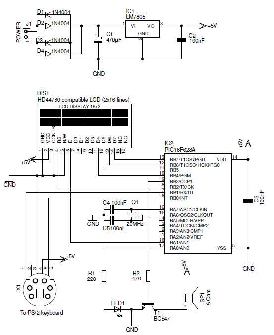
This PIC-based hardware circuit accepts texts from a PS/2 keyboard and converts it into a Morse code audio signal. The described circuit utilizes a PIC microcontroller to interface with a PS/2 keyboard, allowing for the input of alphanumeric characters. The...

The LED meter circuit is more compact and simpler than its analog equivalent, making it a common choice in audio equipment. This circuit utilizes the LM3915 integrated circuit (IC) and operates in a logarithmic mode. It comprises a single...
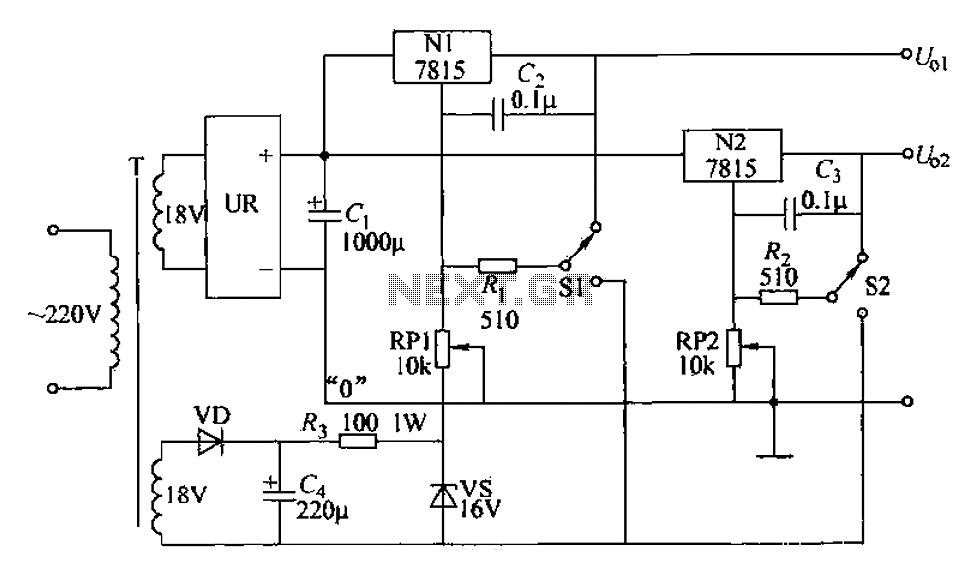
An adjustable dual voltage power supply circuit is presented, suitable for frequent experimental use. The current output does not exceed 1A, and both voltage outputs are adjustable. The circuit utilizes N1, N2, and 78 series three-terminal voltage regulator integrated...
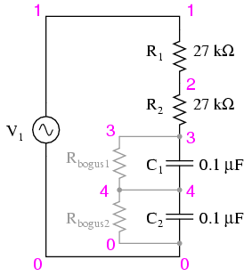
Construct the circuit and measure the voltage drops across each component using an AC voltmeter. Additionally, measure the total (supply) voltage with the same voltmeter. It will be observed that the individual voltage drops do not sum up to...
This schematic represents an FM transmitter capable of delivering an output power of 3 to 3.5 W, operating within a frequency range of 90 to 110 MHz. While the stability of the circuit is acceptable, the integration of a...
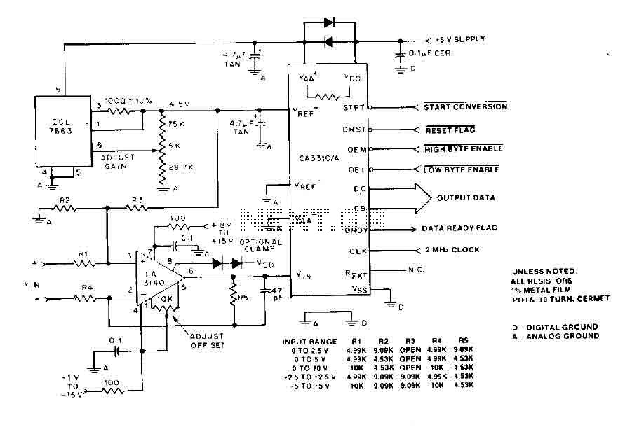
The BiMOS CA3140 operational amplifier offers excellent orientation capabilities for high bandwidth signal inputs and can swiftly adjust the energy output at its terminal CA33IO WINE. The CA3140 can also operate close to the negative supply rail. If the...