
Simple LED blinking using PIC16F877A

The circuit design consists of the PIC16F877A microcontroller, which serves as the central control unit for the LED blinking operation. The two LEDs are connected to specific GPIO (General Purpose Input/Output) pins of the microcontroller, allowing for individual control of each LED. A resistor is typically placed in series with each LED to limit the current and prevent damage to the LEDs.
The operation of the circuit is governed by a simple program written in assembly or C, which is uploaded to the microcontroller. The source code is derived from the existing 16F template, which provides a framework for initializing the microcontroller and configuring the GPIO pins. The code includes a loop that toggles the state of each LED at defined intervals, creating a blinking effect.
For power supply, the circuit can be powered using a standard voltage source compatible with the PIC16F877A, usually 5V. Proper decoupling capacitors should be placed near the power pins of the microcontroller to ensure stable operation.
This simple LED blinking project serves as an introductory exercise in embedded programming and microcontroller interfacing, demonstrating fundamental concepts such as GPIO control, timing, and basic circuit design. The versatility of the PIC16F877A allows for further expansion of the project, such as adding more LEDs, incorporating sensors, or implementing user input mechanisms for enhanced functionality.This is a simple LED blinking project using PIC16F877A. Basically there are only 2 LEDs, connected to PIC16F877A and the source code is being modified from the 16F template.. 🔗 External reference
Related Circuits
This document outlines the theory behind a high-speed control scheme for an LED display screen circuit. The circuit utilizes the MCS51 series microcontroller to manage the LED display. A 62512 random access memory (RAM) is employed for data storage,...
This schematic represents a version of a simple LED chaser. A 555 timer is not utilized due to its high cost at local electronics stores, which is over $4 CAD. Instead, an oscillator is constructed using two sections of...
The microphone amplifier/modulator is built around the LM324, which is a quad operational amplifier that provides sufficient quality amplification for the voice captured by the condenser microphone. The LM324 is a versatile quad op-amp that consists of four independent, high-gain,...

This liquid level sensor electronic circuit diagram utilizes a common CA3410 operational amplifier integrated circuit (IC). The sensor employs two plate sensors (or probes), one designated for detecting high liquid levels and the other for low liquid levels. If...
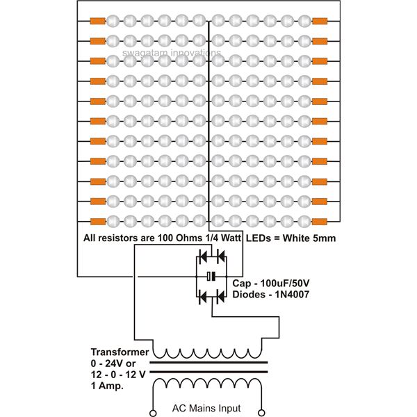
The use of white LEDs for home illumination is gaining popularity due to their high power efficiency. The diagram illustrates a simple circuit configuration that consists of multiple LEDs arranged in both series and parallel. In the LED tube...

The voltage at the anode and cathode of the diodes is checked to determine whether they are conducting. There is confusion regarding the current source and how to determine the state of the diodes for input combinations (00, 01,...