
LED Chaser circuit

The LED chaser circuit consists of a series of light-emitting diodes (LEDs) that illuminate in a sequential pattern, creating a visually appealing effect. The core of this circuit is the oscillator, which generates a square wave signal to control the timing of the LED illumination. By using two sections of the 4011 NAND gate, the circuit achieves oscillation without the need for a more expensive 555 timer.
The 4011 NAND gate is a quad 2-input NAND gate IC, and in this application, two of its gates are configured to create a flip-flop oscillator. The output of the oscillator drives a series of LEDs connected in a cascade configuration. Each LED is typically connected through a current-limiting resistor to prevent excessive current flow, which could damage the LEDs.
The frequency of the oscillation can be adjusted by varying the resistor and capacitor values in the timing network connected to the NAND gates. This allows for customization of the chaser speed, providing flexibility in the visual effect. The circuit can also be expanded by adding more LEDs, creating longer chaser patterns, or by integrating additional NAND gates to modify the behavior of the chaser effect.
Overall, this LED chaser circuit is not only cost-effective but also serves as a practical example of digital logic applications in creating dynamic visual displays. The use of the 4011 NAND gate simplifies the design while maintaining a robust performance, making it suitable for various hobbyist and educational projects.This schematic is version of a simple LED chaser. There is no 555 timer used because at my local electronics store they are over $4 Cdn. Instead, an oscillator made up of two sections of a 4011 NAND gate is employed. This chip is very inexpensive and extremely common.. 🔗 External reference
Related Circuits

There are three switches that represent a binary number, and according to the combination of those switches, the number of lit LEDs changes to represent that binary number. There is a question regarding how to provide equal current and...
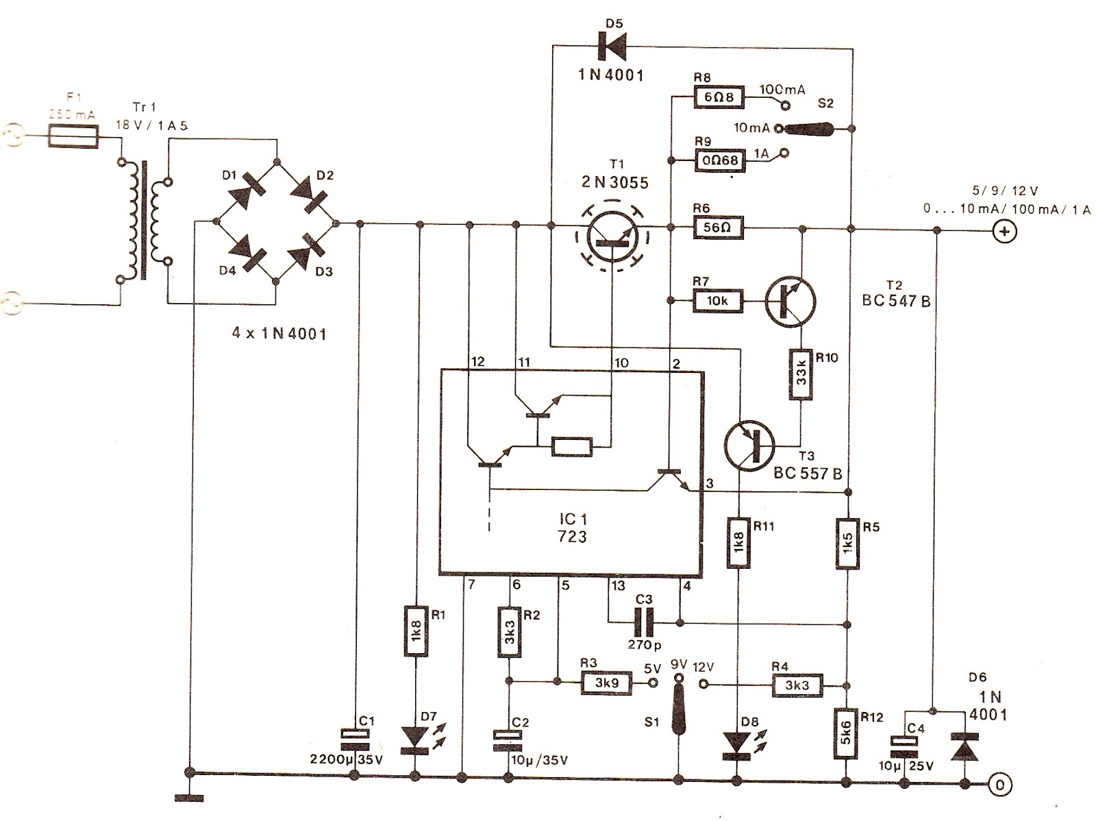
The output voltage can be increased easily by placing a resistor in parallel with Ra until it reaches precisely 5.0 V. Switches S1 and S2 are preferably SPDT types with a center position, but three-way rotary switches can also...
The figure illustrates an NE555 frequency modulation (FM) circuit. In this circuit, pin 7 of the NE555 is connected to an FM modulation section that consists of resistor R5 and capacitor C2, although the frequency range is somewhat limited....
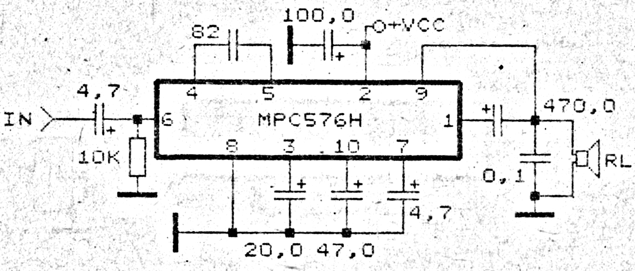
This amplifier circuit exhibits good sound quality. Although it does not provide high output power, it is capable of producing both soft and loud sounds reliably. The circuit utilizes a single IC, the MPC576H, along with several supporting components....
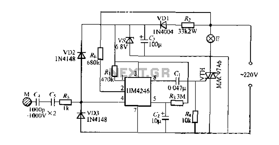
Development and production of a specialized touch dimmer integrated circuit. This circuit features four lighting functions: dark, medium, light, and a touch-sensitive trigger on all four sides. It has low harmonic radiation emission, high touch sensitivity, and stability. It...
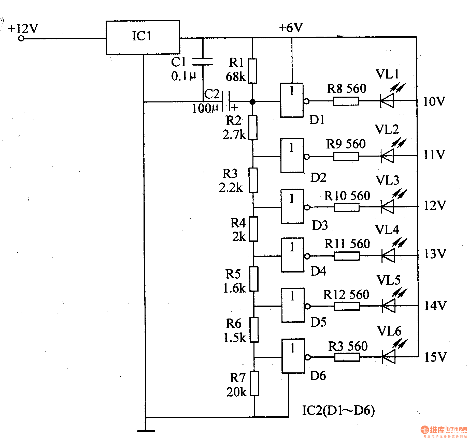
The LED car voltmeter comprises a filter circuit, a voltage distribution filter circuit, a voltage amplifier circuit, and an LED display circuit, as illustrated in Figure 7-77. The regulator filter circuit includes a 3-terminal IC (IC1) and a filter...